UCC28180: 网侧输入低穿偶发PFC MOS过流烧毁

Part Number: UCC28180

Tool/software:

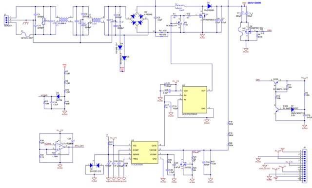
PFC工作环境:网侧220V市电输入,380V输出,设备为无线充电设备发射端,UCC28180用作boost pfc供电,设备满载功率为800W,电路可参考下图
问题现象:在设备满功率运行时网侧出现短时低穿,将PFC MOS击穿,经过后续复现,捕捉到PFC电感的电流波形ch4以及PFC输出电压波形ch1,可见此时有持续8ms左右的40A电流通过

问题点:1、查阅UCC28180数据手册以及论坛类似问题后,猜测该大电流出现的原因是因为此时VCOMP引脚电压在低穿发生时抬升,低穿结束时由于VCOMP过高导致UCC28180内部电流环增益M1过大,所以此时网侧恢复会导致输出有大电流,基于这种情况,请问如何进行修改避免出现MOS烧毁?

2、电路设计中的网侧过流保护ISENSE在低穿发生时未生效,目前不知道为何,望给出建议。

  • Hello Miao, 

    Here is a machine translation of your text into English: 

    "  PFC operating environment: Network side 220V mains input, 380V output, equipment is the transmitting side of wireless charging equipment, UCC28180 is used as boost pfc power supply, equipment full load power is 800W. The circuit can be referenced from the following figure

    The problem is that a short period of low breakdown occurs on the net side when the equipment is operating at full power, and the PFC MOS breaks down. After the reoccurs, the current waveform ch4 of the PFC inductor and the PFC output voltage waveform ch1 are captured. This is where we see 40 A passing for about 8 ms

    Question point: 1. After consulting the UCC28180 data sheet and similar forum questions, guess the reason for this large current is because the VCOMP pin voltage is raised at low wear-through and the UCC28180 internal current loop gain M1 is too large at the end of low wear-through due to high VCOMP. So the net-side recovery can cause a high current on the output. Based on this, how can I make changes to avoid MOS burnout?

    2, the net-side overcurrent protection ISENSE in the circuit design is not effective when low breakdown occurs. At present, I do not know why, I should like to make a recommendation.  " 

    It is not a perfect translation, but I believe that I understand the problem and your questions. 

    To restate the problem: 
    PFC works okay at 800W load while 220Vac is present.  AC voltage is removed for approximately 160ms.  During this time Vout decreases and VCOMP increases until VCOMP is clamped to its limit at ~5V.  When AC voltage comes back, VCOMP is too high and allows very high peak current while Vout is rising back toward regulation.   

    From the green waveform we can see that high peak switching currents (around 50~60A peaks) happen for ~1ms, then switching stops and ~32A dc flows for ~3ms, then this current decays exponentially to zero for ~4ms more.  I agree that the MOSFET burns out after 1ms of 50A+ peaks.  

    For your second question, we expect that peak-current-limit (PCL) should limit the peak current to protect the MOSFET.  
    However, the schematic diagram image too small with low resolution and I cannot see the component values in your design. 
    Please repost a larger, clear schematic image, or insert a PDF file of your PFC schematic, so that I can review the component values.  

    From what little that I can see, it seems that C18 (2.2uF) on "ACSNS" signal is too big, and delays detection of loss of AC too long.  I suggest to make its value much lower so that Loss of AC is detected after ~40ms. 
    Then "PFC_OFF" can be driven High much sooner and VCOMP will be discharged when the AC line voltage returns. 

    Regards,
    Ulrich