Because of the holidays, TI E2E™ design support forum responses will be delayed from Dec. 25 through Jan. 2. Thank you for your patience.

This thread has been locked.

If you have a related question, please click the "Ask a related question" button in the top right corner. The newly created question will be automatically linked to this question.

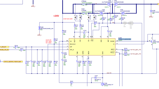
TPS4811-Q1: High side driver is not oing into shutdown mode

Part Number: TPS4811-Q1

Tool/software:

Hello,

we are using TPS48111LQDGXRQ1 IC as a high side switch for motor drive.

Currently ECU is taking very high current in sleep mode.and after investigation we found this IC is taking much current in sleep mode. With INP pin gate driver is in disable state.

EN/UVLO pin is at greater than 2.2V almost 6V.

as per datasheet if we have to put this IC in shutdown mode then need to provide <0.3V to EN/UVLO pin so that IC would only consume 1.6uA.we ties this pin to GND ,still current consumption is high.

Could you please what could go wrong in this case?
  • Hi Smita,

    We will need some more information to figure out what is wrong. 

    How high is the current you are seeing? What is on your load? Is the INP_G pin off? Are you measuring current into VS or from VBATT to VOUT through the FET?

    Thanks,

    Rishika Patel 

  • Hi,

    Question1:How high is the current you are seeing?

    Answer1 :In our ECU we have 2 battery inputs from where these supplies connected to 2 IC's TPS48111LQDGXRQ1.

    so total current of ECU in sleep mode is(where other circuits of ECU is present) :4.39mA

    when VS pin of both iC disconnected then ECU is taking 2.15uA current.it means this IC is taking rest of the current i.e. 4.3878mA

    then we grounded ENA pin (made it low) for both IC then total current is 3.345mA,hence with this only 1mA current is reduced.

     Question2 :What is on your load? 

    Answer2 :There is no load on this IC.Vout is 0V as ECU is in sleep mode.We made this iC in off state via INP and INP_G signal

    Question3: Is the INP_G pin off?

    Answer3: Yes INP and INP_G signals are at OFF state

    Question4:Are you measuring current into VS or from VBATT to VOUT through the FET?

    Answer4: we are measuring current directly at VBATT line.. where battery inputs are connected as mentioned earlier we removed VS supply from both IC's then it reduced the current to uA ,it means all current consumed by 2 IC's TPS48111LQDGXRQ1 even at no load condition (Vout is off)

  • Hi Smita,

    Based on the specifications in our datasheet, we do not expect these devices to draw that level of current in the off state. Please try to test with an EVM.

    Thanks,

    Rishika Patel