Because of the Thanksgiving holiday in the U.S., TI E2E™ design support forum responses may be delayed from November 25 through December 2. Thank you for your patience.

TIDM-02013: Current Sensor Circuit Design

Part Number: TIDM-02013

Tool/software:

Hi

I was exploring the design of Bidirectional EV chargers came across the reference design  wanted clarification regarding few points of Current Sensor

1. Why the Op Amp circuit is used at the output of current sensor.

 2. Will this circuit help in eliminating noises or will it amplify the noises in measurement of input Current.

Thanks 

Rajat

  • Op-amps can certainly amplify noise. This circuit is utilizing the Op-amp as a buffer to get better bandwidth and therefore better dynamic signal response to changes in current.

    Filters typically can be used to eliminate certain frequencies which you do not expect from your signal, but i do not believe the op-amp is fulfilling that purpose here.

    Regards,
    Cody 

  • Thanks Cody for Replying.

    I am also using the same sensor in my design of EV charger of 3.3kW rating to the totem po PFC input of the charger.

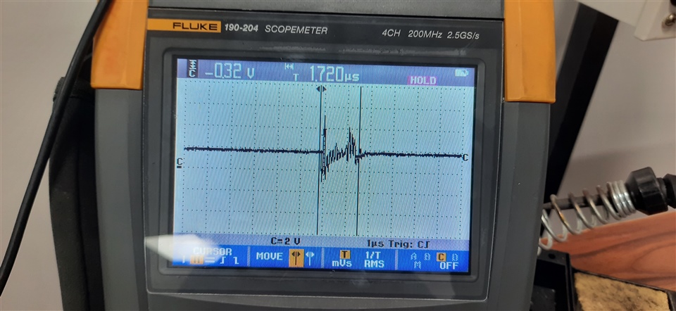
    1.Facing issuse of noise in the output of the current sensor at the instant of PWM pulses wanted to know the possible reason for the noise. 

    2. I have used filter of 16kHz to remove noise but it is persistent.

    3. The test condition is Switching frequency of 100kHz.

    Can you suggest some methods or reason for the noise in the current sensor.

    Enclosed image shows output of current sensor at zero amp current and just PWM switching of the MOSFET

    Thanks