This thread has been locked.

If you have a related question, please click the "Ask a related question" button in the top right corner. The newly created question will be automatically linked to this question.

BQ25622: Parameters confirmation for new project

Part Number: BQ25622


Tool/software:

Hi Expert,

One customer is looking at our BQ25622RYKR (WQFN 18) for a new live streaming microphone.  1-cell battery with full charging voltage 4.35V or 4.4V.

They have few questions hope you can help to answer.

1) Is the chip IEC62368 compliant?

2) Is it safe to charge 350mAh/3C, max charging current 1050 battery?  Because the default charging current of BQ25622 is 1040mA, which is close to the battery charging limit.

3) Customer's battery has NTC value 100kOhm, B4235.  Is BQ25622 suitable to be used?

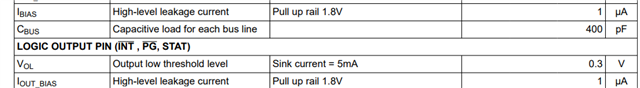
 4)  the pull up rail of I2C, INT, PG, STAT, CE, QON suggested 1.8V.  Can they use 3.3V as their MCU is 3.3V

5) What's the DCR requirement of the inductor 

6)  Can customer further reduce the external circuit if they don't need boost?

7) The BQ25622RYKR package has no thermal ground at the bottom and the BAT pin is only 1PIN. Will it be too hot and any concern with 3A charging? 

Best Rgds,

Stanley

  • Hi Stanley, 

    Please see my comments below. 

    Let me first address question 6. If customer does not require boost they should also consider BQ25622E. It will be very similar to BQ25622, but without the boost mode feature and will therefore be less expensive. In either case required external components will be the same. 

    1) Yes both BQ25622 and BQ25622E are IEC62368 certified. 

    2) This is more of a question for the battery manufacturer. I cannot necessarily say what is a safe charging current for a specific battery. As you mention default charge current is 1040mA and full range for ICHG setting can be found in REG0x02 section in register map portion of the datasheet. Minimum allowable charge current setting is 80mA. 

    3) BQ25622 TS function is intended for use with a 10kohm NTC. 100kohm is not suitable, but TS function on charger IC can be disabled by setting TS_IGNORE bit. 

    4) Yes 3.3V pullup rail can be used. To clarify 1 thing QON should not be connected to an external pullup. It has a built in pullup source. 

    5) Efficiency tables in the datasheet are taken with a inductor with 15mohm DCR. Customer can use an inductor with higher DCR, but efficiency will be reduced some. 

    7) There will be some IC heating and a good layout is important, but the device can operate at 3A output. For example, on the BQ25622EVM with 5V input, VBAT = 3.8V, and 3A charging IC temperature was 64 deg C. 

    Best Regards,

    Garrett