This thread has been locked.

If you have a related question, please click the "Ask a related question" button in the top right corner. The newly created question will be automatically linked to this question.

TPS4811-Q1: Inquiry About Using TPS4811-Q1 in a Battery-Powered System

Part Number: TPS4811-Q1
Other Parts Discussed in Thread: TPS48111Q1EVM

Tool/software:

Hi,

I am designing a battery-powered system that requires a hot-swap controller. I have experience using the TPS4811-Q1 as a MOSFET switch, and I would like to know if it can also be used as a hot-swap controller.

The required functions, such as inrush current limiting and overcurrent protection (OCP), have been tested and verified on the  MOSFET switch. However, I have a few concerns:

  1. Will there be any issues if voltage is applied simultaneously to the VIN and INP pins?
  2. Will there be any issues if voltage is applied to the INP pin first?
  3. Could there be any risk of failure or damage in transient situations, such as when the battery is removable?

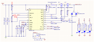
I’ve attached a circuit diagram below for reference. Please let me know if this configuration is suitable for use as a hot-swap controller.

Thank you for your support!

  • Hello Uiuk,

    First off- apologies for the late response.

    To answer your questions:

    1. There is no problem applying both signals at the same time. The TPS48111Q1EVM that we provide actually does this by default.
    2. No explicit issues here as in damaging the device, however do keep in mind that the outputs of the device are in an undefined state when the device is not powered and none of the protection features will be active.
    3. We test for all of the standard ISO7637-2 and ISO16750-2 transients and fault conditions in order to ensure that the device operates correctly. Do you have any specific careabout?

    Note that the INP pin has an active pull-down when the device is powered- meaning that it needs supply voltage in order for the pin to be pulled to ground internal to the device.

    No issues with the schematic that you shared- please just double check with the design calculator at https://www.ti.com/tool/download/SLURB09 for relevant margins.

    Best Regards,
    Tim