This thread has been locked.

If you have a related question, please click the "Ask a related question" button in the top right corner. The newly created question will be automatically linked to this question.

BQ25798EVM: Battery charger IC makes weird switching noises when I go beyond 3.5A of charging current for 1S and 4.1A of charging current for 2/3/4S, but it should go up to 5A

Part Number: BQ25798EVM
Other Parts Discussed in Thread: BQ25798, , BQ25730, BQ25820, BQ25750, BQ24610

Tool/software:

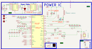
Hello! As mentioned in the title, I developed a battery charger for sodium batteries using the BQ25798, based exactly on the BQ25798EVM PDF schematic switching at 1.5MHz. However, it looks like the chip is not capable of holding a constant current charging for 1S batteries higher than 3.5A and higher than 4.1A for 2/3/4S batteries. E.g I switch from 3.5 to 3.6A for 1S it starts making weird noises and the current drops to 0 and comes back


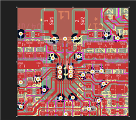
I'm using the same parts as for the EVM, and I tried to follow the pcb routing guidelines as closely as possible, yet it still struggles to hold anything above 4.1A. See the routing and schematic below:
         

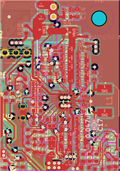
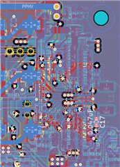
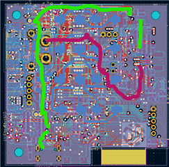
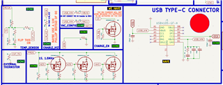
I marked the input power with green and the output with purple. Is there something I am doing wrong with the routing? My input/output trace width is 0.6 mm (for BAT and VBUS pins) and the routes for the SW1 and SW2 pins are 0.3mm, with pcb density of 1oz at JLCPCB. Am I asking the SW lines for too much current? Could they be too narrow?


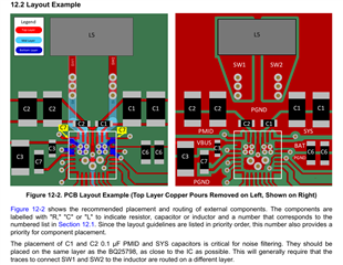
As for the layout example in the chip datasheet, it does seem to have a very solid ground plane around it, but I barely could get any ground plane around (on the top, since my layout is, from top to bottom, POWER, GND, SIGNAL, SIGNAL, GND, POWER) because of the high components density.

Or could it be from one of my settings in the TI CHARGER GUI? Also one thing that I noticed is that I can increase the current slowly as the battery gets charged. For example, my completely drained 2S would only draw up to 3.5A but when I charged it like 10% more it went up to 3.8A. As far as i know the charging current should not depend on the battery charge (and voltage) state, right?

These are my settings in the GUI:

Do you spot anything wrong in the settings, schematic or PCB layout?

  • HI FOCA,

    What do the status and fault registers (0x1B through 0x27) report doing this time?  For example, the charger could be input power limited (IINDPM or VINDPM) because VBUS*IBUS < VBAT*ICHG or, more likely, the IC package is getting too hot and the charger is entering thermal regulation.  It is expected that the IC gets hot above 4A charging.

    Regards,

    Jeff

  • The thermal can't be the case since I placed a heatsink with thermal paste on the chip and there's also a fan blowing air from above on the chip, while the 4A temperature doesn't go above 80C and the regulation temperature is 120.

    As for the fault registers, I get "VBUS_OVP_STATUS" in like 90% of the times and then sometimes the chip also reports "VBAT_OVP_STATUS" at the same time with the VBUS error. See the image below:

    What should I do?

    Also these are my input settings:

    I can't change IINDPM to anything higher than 3A, even tough the ILIM pin is connected to REGN (5V) through a 0O resistor which should've set the current to the maximum 5A.

    For the ABS VINDPM I'm not sure what it is, but if it's the input voltage maximum I've been already getting 20V as input for a long time without any errors so it can't be that. I tried to raise it to 20/21V thinking maybe it has something to do with the charging, but that completely stopped any current from coming in

    And VOC_PCT, I'm not sure what this is either...

    And this is my chip configuration:

  • Hi Foca,

    VINDPM is the lowest input voltage that you want the charger to allow from power supply in order not to crash the power supply.  So set the VINDPM register to slightly below your max current.  If you set too high, that could explain your VBUS OVP errors.  VBAT OVP is determined by comparing BATP pin voltage to VREG register x OVP%.  Can you provide an oscilloscope shot of VBUS, VBAT, SYS and SW1 when these errors occur?

    Regards,

    Jeff 

  • Ok so my charger works on a 20V-5A USB PD contract therefore I should set the VINDPM to about 18V? I got a 100W Anker power brick so it should be more than enough. So for my 20V the VINDPM should be about 18V? If the brick drops below that then it would be a serious problem.

    I don't have access to the VBUS/VBAT/SYS/SW1 lines right now on an oscilloscope (I also have just a 2 channel oscilloscope...). Is the scope shot absolutely necessary on all 4 of them? Let me know to see if I can get a 4 channel scope and provide you with the info.

    It's weird that I can't increase the IINDPM anywhere above 3.3A, even though it clearly states in the device datasheet that it can sink up to 5A... Is it worth it trying to improve this design or should I just go for an alternative chip that doesn't have the switching FETs integrated like the BQ25798? I tried it in the meantime with multiple types of batteries and phone bricks (I got 2, one of 65W and another of 100W so I know when to change them) and it seems like the maximum current it can ever give to a battery is 3.8A, well reliably

    I was looking at the BQ25820 for >4/5S (I want the chargers to be configurable in the GUI) and for <=4/5S I was looking at BQ25730. My project goal is a 100W-capable (80W Actual, since 16V*5A = 80W for Sodium Ion, and even with the 4.2*4 = 16.8*5 = 84W for Lithium Ion it doesn't go above 85W) battery charger using USB PD.

    Would the BQ25820/ BQ25730 be better for my needs, as they don't have the integrated switching FETs problem therefore better thermals?

  • Hi Andrei,

    Yes to VINDPM=18V or lower if you think USB PD can better manage its own output power.

    I forgot to mention that IINDPM max is 3.3A not 5A.  If the datasheet says input current is 5A somewhere, let me know.  The max output from converter is 5A.

    Yes to using a converter with external FETs for easier thermal management.  You might try one of the BQ25750 family members.  It could do all of your battery configurations.

    If only 2 channels then start with VBUS and SYS.

    Regards,

    Jeff 

  • Thank you so much for your support, Mr Jeffz you are so right, the maximum input current is 3.3A, which means the device can possibly ever sink 3.3A*20=66W theoretically... I thought it was 5A!

    Well in that case I will try to move to a new chip, do you have any part number recommendations for one that can sink 100W? I want to make a small USB-C 3.0 powered 1-4/5S battery charger, and the BQ2750 is a bit of an overkill for such a task.

    Could the BQ25730 be good for my project? I want to pick a chip that will not be deprecated and still has a good production lifetime (at least 3 more years from now)

  • Hi Andrei,

    BQ25730 is a good choice but it does not perform auto termination.  It is expecting a gauge to monitor current and then report to the host to report to the charger to terminate charge.  You might consider BQ24610 which is a standalone charger to reduce software effort.  

    Regards,

    Jeff