This thread has been locked.

If you have a related question, please click the "Ask a related question" button in the top right corner. The newly created question will be automatically linked to this question.

BQ76952: ESD Protection

Part Number: BQ76952


Tool/software:

Dear TI Expert,

 We are using low side switching.

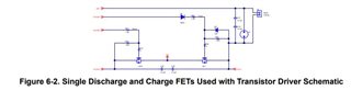
Document Number: Using low side FETs with the BQ76952 Battery Monitor Family

Fig. no: 6-2

Please suggest for E1 Following points Regarding PCB: 

1. Track width

2. Pad Size and Gap

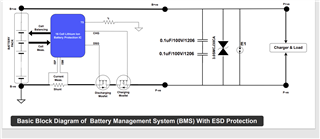
This above arrangement is work for +/- 8KV ESD Test.

Please suggest 45V ESD Bidirectional diode which have 45 to 50V DC Breakdown Voltage.

Thanks 

Rahul Sharma

Lithion Power Private Limited

  • Hello Rahul,

    This ESD Protection Layout Guide is useful to follow regarding PCB. We do not have exact values for the track width, pad size, and gap as they are very dependent on the user's own limitations as well. Usually, the thicker the traces/pads, the better it is for ESD. The smallest impedance to the ESD component is also recommended. 

    Our BQ76952 EVM design files can also be used as reference. We don’t have any personal recommendations for ESD Bidirectional diodes; however, you can use the ones we chose for our EVM.

    Best Regards,
    Alexis

  • Dear TI Expert,

    This is reference TI document BQ76952EVM.

    Please help us to explain following.

    Considering ESD Protection a TVS diode is used at data line but not used in power line .

    What is the Reason?

  • Hello Rahul,

    I’m not quite sure where you got this image from. The image shows an AFE that is not our part. Can you share the reference document link you followed to find this?

    For ESD protection in the power lines (presumably the cell inputs are what you were referring to), it depends on the user’s application and concern. Our part has internal ESD protection at the pins that allow the pins to have a maximum rating of 85V. This is shown in Figure 1-19 and Figure 1-20 of the Pin Equivalent Diagrams application note.

    Users who use external cell balancing will configure it differently as well, as shown in Section 2.2 External Cell-Balancing Circuit Design Using N-Channel FETs of the Cell Balancing application note.

    Best Regards,
    Alexis

  • Dear TI Expert,

    Reference document link: BQ76952EVM User's Guide (Rev. A)

    Considering ESD Protection a TVS diode is used at data line in Fig. 5-12 but not used in power line in Fig. 5-11.

    What is the Reason?

    Thanks 

    Rahul Sharma

  • Hello Rahul,

    Thank you for clarifying which Figures and reference document you were referring too. For the EVM, there is ESD protection in the form of ESD capacitors and spark plugs as well as ESD capacitors across the FETs. You could use TVS diodes if you so desired as well, however, the person who designed the EVM decided not to.

    Best Regards,
    Alexis