This thread has been locked.

If you have a related question, please click the "Ask a related question" button in the top right corner. The newly created question will be automatically linked to this question.

UCC28950: About the derivation of the formula 2

Part Number: UCC28950

Tool/software:

Hi team,

I have an additional question.

Q2

If the transformer primary winding is n1, the secondary winding is n2, and the transformer winding current change is ΔIP, then ΔILOUT/a1 should be derived from the formula n1 * ΔIP = n2 * ΔILOUT.

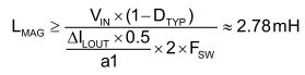
Why is there a coefficient of 1/2 multiplied to ΔILOUT/a1?

> This is to avoid running in voltage mode control.

> This is described in application note slua560 that can be found in the following link.

https://www.ti.com/lit/pdf/slua560

The AN states the following:

"If LMAG is too small the magnetizing current could cause the converter to operate in voltage mode control instead of peak-current mode control. This is because the magnetizing current is too large, it will act as a PWM ramp swamping out the current sense signal across RS."

Why does the voltage mode occur when the magnetizing current increases too much?

Also, why do we multiply ΔILOUT/a1 by 1/2? What is the basis for 1/2?

Why is VIN not VIN-2*VRDSON?

Q3

When LMAG is derived from the formula for the commutation current, I think LMAG is the sum of the transformer Lp and the resonant coil L1. Is that correct?

> Lmag is selected to avoid voltage mode control.

Isn't the magnetizing inductance LMAG the sum of the transformer's Lp and the resonant coil's Ll?

  • Hello,

    In regards to Q2:

    At the time this equation was generated, the author of the application note was trying to keep the design out of voltage mode control.

    A lot of designers do not pay attention the affect of Lmag and Lout on their current sense signal.  If it is too large Imag+diLOUT/a1 is too large the controller will not be controlling the output current.  If these current are to large the design will actually controlling controlling a ramp voltage generated by (Imag+diLOUT/a1) and not the output current.  If this happens the design will operate into voltage mode control.

    If you follow the equation below the magazine current will be 1/2 the reflected output current at (1-Dtyp)

    a1 = Np/Ns = Vp/Vs = Is/Ip


    The output inductor ripple current was designed for 20 % load.  So the equation for LMAG is limit the magnetizing current to 10% of the reflected output current, that is where the 0.5 comes from in the equation.  Looking at this now I would have (Dmax) in the numerator instead of (1-Dtyp).  However this is the how the author chose to select the magnetizing inductance for his design, which seem to work correctly for him a 600 W phase shifted full bridge design.    

    If you wanted to be more accurate you could replace Vin with (Vin - Ids*Rdson) instead of Vin to calculate Lmag you could.   However, selecting the Lmag based on the application not will avoid having the design operate in voltage mode control.

    In regards to Q3.  The magnetizing current of a transformer is based on the following:

    V = Lm*di/dt

    di = (V/Lm)*dt 

    Thank you for interest in Texas Instruments (TI) products.  If you have a related question, please click the "Ask a related question" button in the top right corner. The newly created question will be automatically linked to this question.

    Regards,