Other Parts Discussed in Thread: BQ25792,
Tool/software:
We are using the TPS25751 as the PD controller and the BQ25792 as the battery charger IC in our design. I have a few questions regarding their integration:
-
Can the TPS25751 PD controller by default communicate with the BQ25792 charger IC via the I2C lines, given that the BQ25792 has a specific I2C address?
-
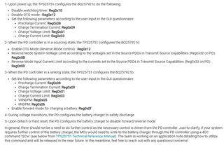
What is the specific application of the ADCIN1 and ADCIN2 pins? Can ADCIN1 and ADCIN2 be connected to the same voltage divider in the circuit?
-
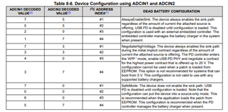
In our design, we have not included an EEPROM since we have a processor in the circuit. The PD controller and the processor are both connected to the I2C bus. Are there any additional considerations or configurations required for this setup?
-
What is the application of the I2Ct_IRQ and I2Cc_IRQ pins?