Because of the Thanksgiving holiday in the U.S., TI E2E™ design support forum responses may be delayed from November 25 through December 2. Thank you for your patience.

LM5158: Issue with boost DC-DC coverter (LM5158)

Part Number: LM5158

Tool/software:

Dear Engineers,

I have designed a variable-output boost DC-DC converter (LM5158RTER) to step up 5 V to 40 V. However, after receiving the PCB, I noticed that the output is fixed at 4.98 V, even when adjusting the potentiometer in the feedback loop. I have attached the schematic for your reference. Could you please review it and let me know if you identify any issues?
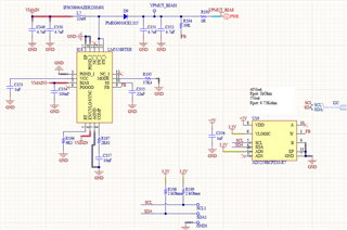
One observation I made is that in the reference design, a resistor divider is used to feed the EN/UVLO pin, whereas I have directly connected this pin to VMAIN (5V). Additionally, the reference design includes a capacitor directly connected to GND in parallel with the current circuit (R197, C357) on the COMP pin. In contrast, I used a different configuration. Also, in the reference design, RT is connected directly to GND, while I have used a resistor (R196) in my design. Could you please advise if these differences could be the cause of the issue, or if there are other areas I should investigate?

  • Hi Bahnam,

    thank you for using the E2E forum.

    On the FB pin you need a resistor divider which divides the output put voltage down to 1V.

    So this means in addition to Resistor a resistor R194 to FB you need another Resistor from FB to GND.

    Best regards,

     Stefan 

  • Hi Behnam,

    What is the output current you designed for?
    Did you check if your potentiometer is working like expected? So does it change the resistance?

    Is the LM5158 even turning on?

    Can you please send some scopeshots of Vin, Vout and switchnode?

    What is the reference design you are referring to?

    Best regards

    Moritz

  • Hello Stefan,

    In fact U19(AD5259BCPZ1) is a digital potentiometer, so I think we have you you mentioned from FB to GND, right?

  • Hello Moritz,

    - What is the output current you designed for? at this potent we do not care much about this, but I think it is at leas 200mA

    - Did you check if your potentiometer is working like expected? So does it change the resistance? No, It is not very easy to measure it in fact.

    - Is the LM5158 even turning on? How can check this?

    Can you please send some scopeshots of Vin, Vout and switchnode? Sure, I will do it as soon as possible 

    What is the reference design you are referring to? I mean this design in simulation examples for LM5158:

  • Hello Behnam,

    at this potent we do not care much about this, but I think it is at leas 200mA

    You should care about it when doing a design. Components like the inductor strongly depend on this.
    22uH would be too high for switching at 2MHz with 200mA load current.

    No, It is not very easy to measure it in fact.

    Then you should for further checks change it with a normal resistor to see if the poti is the rootcause.

    How can check this?

    You measure if it is switching.

    I mean this design in simulation examples for LM5158:

    Ok, but this also has a RT resistor. This resistor is necessary.

    Best regards

    Moritz

  • Hello Moritz,

    I did the following measurements:

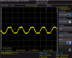
    EN=4.98V, FB=1.8V, SS=3.48V, SW=4.98V, I add the scope view of SW also on the the post itself.

    SW signal:

    Please let me know if I need to measure more parameters?

    Regards

  • Hi Behnam,

    Please measure the signals i requestad above in one scopeshot:

    Vin, Vout, switchnode and comp.

    The switchnode signal looks strange. how is it measured? Is it AC coupled?

    Regards

    Moritz

  • Hi Moritz,

    Thanks a lot for your help, the issue was the POT, related to the address of the I2C bus, not it is working properly and LM5158 switches at 200MHz: