UCC28064A: Is switching expected at VINAC 0v points?

Part Number: UCC28064A

Tool/software:

Hi - I've got a PFC circuit running taking a 115V AC and generating 400V DC.  Target output is around 700W and I will be doubling the circuit up once everything is running sweetly to get 1.2kW+

At the moment I'm getting awful PF figures (of around 0.3 at no load, peaking at 0.7 at about 200W and dropping back to about 0.5 at 500W+)

Obviously the intention is a near-unity PF, so something isn't right.  Upon analysing the switching pulses, when the VINAC signal drops around 0V, the GDA and GDB outputs both stop switching and re-start again when VINAC rises on the next half-cycle.  The switching timing is fairly steady during the half-cycle when they are active and you can see it varying the on/off times as VINAC rises and falls.  (My test load is 100% resistive at the moment - a bunch of heater elements keeping my feet warm).

Should this stop-start be expected at the 0V points, or should the switching continue throughout the cycle?  At the moment they are off for about 20% of the time.  And significantly as the switches come back on, they start in-phase with each other and do not settle into interleaved mode until the waveform is at around the peak, so we are only running in interleaved mode for about 40-50% of the time.  Is that also to be expected?  That the two phases are in-phase to start with?

I've tried with/without the funky diode arrangement for low-VINAC distortion improvement.  With, no improvement.  I've also tried playing around with enabling and disabling both BRST and PHB trigger points.  All with no effect.
My inductors are currently 250uH, and I'm wondering if they are too small as I've had to increase switching freq (increasing RTSET) to prevent current walk-up.  But would too-small inductance here prevent the switching at low VINAC?  Would putting a 100uH in series with them be an easier/sensible solution rather than re-winding the custom magnetics?
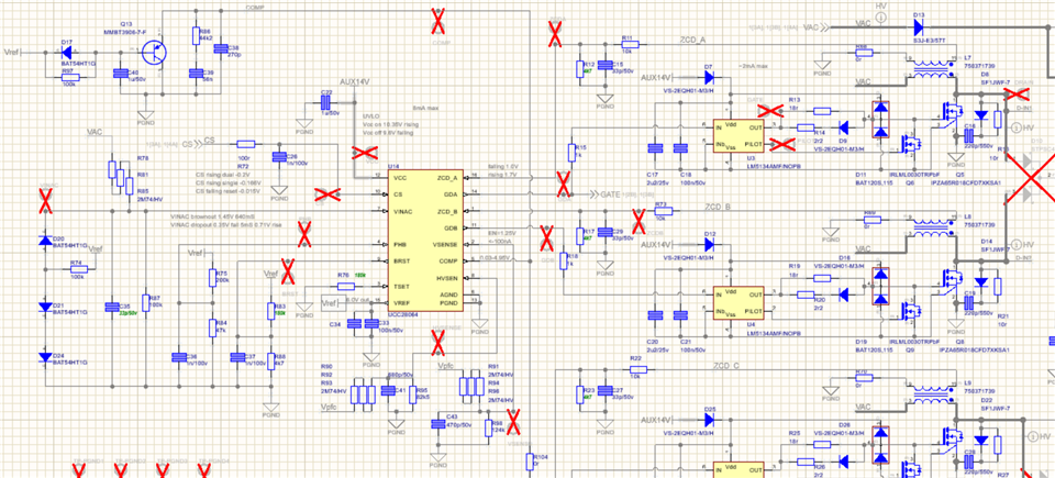
  • Hello Tom, 

    Definitely something is not right, to get the results and behavior that you are getting. 

    Switching may or may not continue through the zero-crossing points, depending on the ZCD signals. 
    The next switching cycle is not automatic, it is triggered by the ZCD signal of the previous switching cycle.  

    ZCD (zero-current detection) is determined by two criteria:
    1. The voltage at the ZCDx input must exceed a 1.7V-threshold during the corresponding MOSFET's off-time (during the inductor demagnetization time), and
    2. That ZCDx voltage must then fall below a 1.0V-threshold at the end of demagnetization to trigger the next MOSFET turn-on.

    If the inductor turns-ratio is such that either of those voltage thresholds cannot be met, then no subsequent turn-on will happen and the switching stops (in that phase). 
    Since the two phases are likely to have nearly identical properties, it is highly probable that both phases stop switching about the same time.
    Once ZCDx is lost, it cannot be regenerated spontaneously.  It needs some other pulse source to restart switching. 

    A built-in "watch-dog" timer delivers a restart pulse to both phases every ~210us if either one of them loses ZCD.  This timer is reset when both ZCDx signals are firing, or ZCDA alone if Phase-B is shut down by PHB, so it doesn't interfere with normal running. 

    The two phases will always restart in-phase, but should migrate to out of phase operation within several switching pulses. 
    They also start in-phase each cycle if OCP is triggered at the CS input (see datasheet).  But that (OCP) doesn't make sense since OCP usually occurs near the peak of the line current, not along the "walls".  Check to see if the in-phase switching occurs at ~210us period.  If so, then the ZCDx signals are not in spec to sustain switching until the input voltage has risen to some level. 
    The resistor dividers on ZCDx (R11 and R12 for example) are unusual, and may contribute to the problem. 
    Also, I recommend to set R11 to at least 20kR, to avoid excess current into and/or out of the ZCD input.   

    250uH does not sound like "too small" of an inductance.  However, there is no information about the ZCD-winding turns ratio, so that must be checked.  
    Generally, if the PFC design is done using the UCC28064A Excel calculator tool, then it should work correctly (barring assembly error or extremely bad pcb layout). 
    https://dr-download.ti.com/design-tools-simulation/calculation-tool/MD-0YHPu8SvFB/01.00.00.0C/sluc645c.zip 

    Regards,
    Ulrich