UCC21225A: Wrong sync rectifier gate connections

Part Number: UCC21225A
Other Parts Discussed in Thread: LM5045

Tool/software:

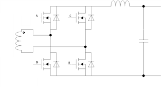
We use two UCC21225 chips to drive 4 synch rectifier MOSFETs in a full bridge config., using a transformer single winding output (no center tap). One LM5045 controls two UCC21225 chips in this config. See schematic below which shows our output bridge rectifier cct. When the transformer dot end goes +ve, FETs A & B should be driven on and C & D off ; and vice versa when when the dot end goes -ve. The two UCC21225's drive gates A, B, C, & D.

However in our board the MOSFET gate connections to the UCC21225's  have been accidentally reversed, which means the transformer is connected in reverse polarity wrt the MOSFETs; i.e., when the dot end goes +ve, FET's C & D are on, and A & B off, and vice versa when the dot end is -ve.

We cannot easily swap the transformer-MOSFET connections; the easier method is to swap the MOSFET gate-UCC21225 connections (A/B - C/D) ; or we can swap the LM5045 SR1 -SR2 connections. 

Are both or either of these fixes acceptable? The benefit of swapping SR1 /SR2 pins is that the gate drive - UCCC21225 connections remain optimal wrt PCB layout.
  • Hi Marcello,

    Both swapping the MOSFET gate connections and MCU output connections would technically work.

    I would lean towards swapping the MCU output connections as the preferrable solution.

    The concern with swapping the MOSFET gate connections would be the added gate loop inductance on the PCB layout. Another concern would be maintaining the channel to channel creepage in the layout to avoid any cross talk between channels or between drivers.

    Hope this helps.

    Regards,

    Hiroki

  • Thankyou. I agree with your preferred solution and I fixed it that way, and it now works. However another problem has occurred that I cannot explain: the LM5045 SR outputs are toggling even though there is no PWM output signal (HO/LO); this only occurs briefly, during a one time hiccup that occurs after startup. Essentially the DC output voltage comes up twice: the first time it overshoots by 10V (reaches 55V vs 45V setpoint)  then drops to 0V in about 200usec, then comes up a 2nd time smoothly, with no overshoot, and stabilizes /runs normally at 45V (proper DC output), so the cct is actually  regulating properly. I think the FB loop is causing this hiccup and needs to be tuned; but aside from that, the bigger problem is the discharge of the output; 50V drops to 0 in 200usec and with about 500uF load capacitance, this requires a very large current. At the first startup, as soon as the output overshoots, the PWM (LM5045 HO/LO) immediately stops. Then both SR outputs of the LM5045 start toggling in unison at the designed sw freq (330kHz) while the PWM HO/LO outputs remain stopped; furthermore both SR1 and SR2 are in phase with each other (they have the exact same waveform). So it must be that the sync MOSFETs are discharging / shorting the output (during the hiccup) which, aside from conducting high current, are being subjected to very high voltage pulses - reaching 175V, as the SR's toggle off.

    Do you know what causes the LM5045 to enter this mode of operation? I don't see anything in the data sheet to help me in this regard.