Tool/software:
Hi Ti Team
I want to use 4.7kohm instead 4.75kohm resistor for 3.3v vout selection then what will happen TPS61094 ?
Please reply as soon as possible
Hi Sanjay,
It might work for some pieces, but we don't guarantee the reliability for all pieces.
Best Regards,
Travis
Hi Travis,
One more issue found in TPS61094 IC.
Pls find our designed as per your reference design

Issue: When NBIoT demanding the current from TPS6109 Vout pin, then IC not able to charge supercap from 0V but battery can support the current.
if battery is supporting it the the superacap shoul be charge because voltages are fine as per below
Vin: 3.67V
Vout: 3.65V
Vout selection: 3.3V ....by external resistor value is 4.75Kohm
VCHG: 2.7V ....by external resistor value is 6.65Kohm
ICHG: 10mA ....by external resistor value is 13.0Kohm
" Why not charge supercap"
Hi Sanjay,
Please measure VIN(pobe near IC) and VOUT voltage when NBIoT demanding the current from TPS6109 Vout pin and the IC stop charging.
Most likely R13 is generating voltage drop which causes VIN falls below 3.3V. So the IC will quit charger and enter boost mode and VOUT is supported by SUP (regulated at 3.3V).
Best Regards,
Travis
Hi Travis,
Ok got it.
But when our product goes to sleep, there is no demand for current for the entire 24 hours. It only demands current for 1 minute in 24 hours, even though TPS61094 IC stops charging.
Please give solution for charging because all voltages are fine during sleep mode.
Hi Sanjay,
You mean the IC stop charging when current is demanded or not?
Did the IC stop charging when sleeping mode? Even when no current is applied on Vout?
Best Regards,
Travis
Hi Travis,
You mean the IC stop charging when current is demanded or not?
Yes,
IC stop charging when current is demanded. "why not charge after current demanded"
Did the IC stop charging when sleeping mode? Even when no current is applied on Vout?
During charging of the supercap if the current is demanded, the IC will stop charging,
If no demanded the current during charging, no problem is detected.
Hi Sanjay,
So when do you need SUP to power Vout and when do you need SUP to get charged?
If you need SUP to power Vout when load is applied, then the R13 should be applied.
If you need SUP to power Vout only when vin is disconnected, then you should short R13.
Best Regards,
Travis
Hi Travis,
1. Please give the solution why IC stop charging and how can improve the charging process as per design?
2. What is the Max. output current (I_Load) as per our schematic? Our Load Current goes up to 700mA.
3. What are the concequences if load drives more current ILoad max in Boost mode?
Hi Sanjay,
1. Please give the solution why IC stop charging and how can improve the charging process as per design?
Short R13
2. What is the Max. output current (I_Load) as per our schematic? Our Load Current goes up to 700mA.

It depends on VSUP. I think the IC support 700mA Iout when VSUP>1.1V
3. What are the concequences if load drives more current ILoad max in Boost mode?
IC input current is limited. Vout will drop if the Iout further increase.
Best Regards,
Travis
Hi Travis,
Thank you for response
1. If we short the R13 then the maximum current drawn from the battery during the transmission and life of the battery will be reduced.
2. In auto buck- boost mode: During transmission, our meter taking pulse current around 500mA for 90second, the supercap voltage drops to 0.7V from 2.7V, and the TPS61094 IC enters shutdown mode, thus stopping charging."How can the supercap be re-charged?"
Best Regards,
Sanjay Katre
Hi Sanjay,
I'm sorry that I don't understand your requirement. You don't want the 90s 500mA load to consume power from the battery, and your super cap capacity cannot support 90s 500mA load neither. Where do you want the output power to come from.


Please give the power path you would like to have so that I can give you advise. Do you want the 90S 500mA power to come from Vin or from SUP?
Best Regards,
Travis
Hi Travis,
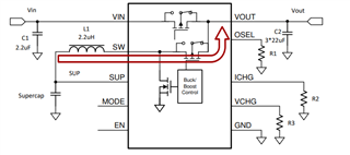
1. During the transmission power path, as shown in fig.1.

Fig.1
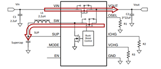
2. After completing the transmission power line as shown in fig.2, but the IC fails to recharge the supercap, resulting in a voltage drop of 0.7V during transmission.

Fig.2
Please give the feeback on
Hi Sanjay,
Your device cannot recharge because your super cap capacity cannot support 90s 500mA load. So the SUP is discharged to 0.7V and triggered VSUP UVLO shutdown. Your solution is increase super capacitor capacitance so that the supercap energy can support 90s 500mA load.
Best Regards,
Travis
Hi Travis,
Thanks for replied.
So the SUP is discharged to 0.7V and triggered VSUP UVLO shutdown.
1. Why not switch to auto buck mode? because Vin=3.66V (After R13), Vout=3.6V & Vout Selection=3.3V
2. How to exit UVLO shutdown?
Hi Sanjay,
This thread is taking too long and I recommend sending e-mail to travis-wang@ti.com and jing-ji@ti.com
Best Regards,
Travis