TL494: Questions about DTC.

Part Number: TL494

Tool/software:

Hello guys,

One of my customers is evaluation TL494.

At this moment, they have the following questions.
Could you please give me your reply?

Q1.
Do you have any graph of DTC input voltage VS Dead time percentage?

Q2.
In the customer evaluation, on duty became 0% at 2.5V DTC voltage.
Is this cause device variation?

Q3.
How much is the variation between DTC input voltage VS Dead time percentage?

Your reply would be much appreciated.

Thank you and best regards,
Kazuya.

  • Hi,

    Q1

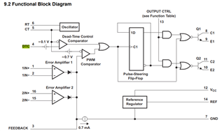
    No, we do not. This is ok to estimate based on the datasheet below block diagram after you pick up RT and CT.

    Designing Switching Voltage Regulators With the TL494 (Rev. E) provides how to calculate charging current to CT. DCT + 0.1V is a threshold for you to estimate the dead time.

    Q2

    Zero duty cycle is with DCT at a a range from device to device, DCT can be as high as 3.3V. So yes, there is quite variation from part to part.

    Q3

    It is quite a lot as you see for 0 duty cycle DCT can be in a wide range from your 2.5V to 3.3V. The reality at min could be further lower than your 2.5V. But we do not have a specs.

  • Hi Hong,

    Thank you very much for your reply.

    Could I ask you a few additional questions as the below?

    Q1.
    According to the customer evaluation result, the on-duty is 42% when DTC is 0V.
    Is this a reasonable value? (Typical value is 45%) 

    Q2.
    How much does this maximum on-duty vary between individual parts and temperature? 
    For example, is it about +/-10%? Or +/-20%?

    Q3.
    Their evaluation conditions are the below.
    VCC=+12V, RT=15.475kΩ (15kΩ+475Ω), CT=1000pF, FB=OPEN.
    Is "FB=open" condition no problem?

    Thank you again and best regards,
    Kazuya.

  • Hi,

    1.

    It is reasonable

    2.

    This specs is not with min and max so it is possible with +/-20% 

    3.

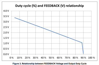
    FB voltage is affecting max duty cycle. See Using error amplifiers to remove error and variance for duty cycle change along with FB voltage: page 2

  • Hi Hong,

    Thank you very much for your reply.

    At this moment, the customer has the following questions.
    Could you please give me your reply?

    Q1.
    The customer want to get ON Duty variation data because ON duty spec doesn't have Min/Max value if you have.
    Do you have the data? 

    Q2.
    They think they can set duty about only 35% in the on duty worst case because the variation rate is about +/-20%.
    Is their thought correct?

    Q3.
    What is the cause of this variation?
    Is it voltage shifting of internal triangle oscillator? 
    Or is internal DTC offset voltage shifted?
    And or is internal oscillator frequency the cause?

    Thank you again and best regards,
    Kazuya.

  • Hi,

    1. 
    No I do not have the data. To get the data please contact your TI local office or through a TI local support and you need to provide your business detail. This is TI confidential so cannot be disclosed on E2E even if the data is available.

    2.

    I think you mean to get max duty cycle 35%, yes this should be ok.

    3.

    DTC variation is one based on the datasheet. Oscillator should have tolerance effect along with drive rise and fall time variations also based on the datasheet.