Because of the Thanksgiving holiday in the U.S., TI E2E™ design support forum responses may be delayed from November 25 through December 2. Thank you for your patience.

TPS923652: Not working properly

Part Number: TPS923652

Tool/software:

Translated from Japanese to English using Google Translate.

I am using TPS923652 to drive LEDs, but they are not working properly.

Boost mode

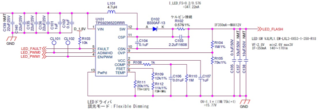
Vin = 5V

4 LEDs (Vf=3V x 4)

Maximum current 350mA

Switch frequency = 1MHz (FSET 23KOhm to GND)

TEMP pin 20Kohm to GND

COMP pin 1Kohm to 0.01uF to GND

VCC pin 1uF to GND

R-sense = 0.576ohm

C-sense = 0.22uF

L = 4.7uH (Max 4.2A)

output diode Iout = 3A Vf = 0.5V

I tried all dimming modes, but the SW pin only outputs the first pulse.

Analog dimming and flexible dimming cause a fault.

I want to use flexible dimming. (Used for camera flash)

Although there is no fault in PWM mode, the SW output is only one pulse with the EN PWM signal, but the L pulse is 3us instead of 1us at 1MHz, so it does not work, so it is tested in analog dimming mode for easier understanding.

In dimming mode, after outputting an H pulse of EN = 5us from EN/ADIM=L, it waits 300us before switching to analog dimming mode.

After EN = H, a 10KHz PWM signal is input to ADIM.

I tried various wait times from EN = H to inputting the PWM signal, but the result did not change.

With the second PWM pulse from ADIM, the first SW output L pulse is output for about 100ns.

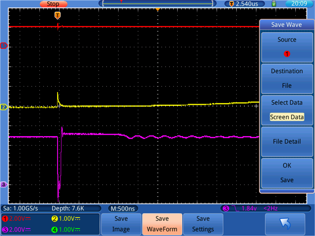
The COMP pin is about 0.8V at the falling edge of the first SW pulse, but it drops to 0V in about 10ns.

After that, the SW pin does not operate at all and the COMP pin slowly rises to 0.8V (depending on the PWM duty) over about 10us, but the SW pin still does not output a pulse and after a while it becomes a Fault.

I would like to operate it in analog dimming mode at least.

What is wrong?

  • Hi Teruyuki,

    output diode Iout = 3A Vf = 0.5V

    I assume you are talking about the Schottky diode here. You are operating TPS923652 in Vin = 5V, Vout = 12V, Iout = 350mA in Boost topology. Am I correct?

    May I understand how do you set the OVP resistor divider? If possible, could you provide your schematic for me to have a look? We can talk through e-mail if needed.

    Best Regards,

    Steven

  • Dear Steven Li

    I assume you are talking about the Schottky diode here. You are operating TPS923652 in Vin = 5V, Vout = 12V, Iout = 350mA in Boost topology. Am I correct?

    Yes

    The OVP is 1Mohm and 75kohm.

    The OVP pin never exceeded 1.1V.

    This is the circuit diagram.

    I tried 22uF / 10uF / 1uF output capacitors for C137, but the results were the same.

    C103 has been changed to 0.22uF. (From the results of TPS92365x_Cal_Tool_V1p2_preview_version.xlsm)

    C106 has been changed to 1nF.

  • Hi Teruyuki,

    Please set C103 back to 2.2uF or 1.5uF. The preview-version calculation tool may not present a correct result. Please refer to Equation (11) from the datasheet.

    Could you set EN/PWM pin and ADIM/HD pin to constant-high voltage level, probe the SW and COMP pin, and then show me the oscilloscope capture (two traces in one figure)? Thanks.

    Best Regards,

    Steven

  • Dear Steven Li

    Should EN and ADIM be set to H level at the same time?
    What is the best procedure for operation after soft start?
    (What dimming mode should it be?)

    EN and ADIM are controlled by a microcontroller.
    This is for camera flash use, and the maximum lighting time is expected to be around 200ms, so it would be difficult from the perspective of heat dissipation to keep the LED on at 350mA.

    Also, what value should I use for C137 to capture the waveform?
    I have 22uF/10uF/4.7uF/1uF available.

  • Hi Teruyuki,

    Please use 10uF for C137 to capture the waveform.

    This is for camera flash use, and the maximum lighting time is expected to be around 200ms, so it would be difficult from the perspective of heat dissipation to keep the LED on at 350mA.

    I understand. For waveform capture, please use analog dimming mode, keep EN/PWN = constant high and input a duty cycle as large as possible that is within the heat dissipation capability of the board & LED to the ADIM/HD pin. Thanks.

    Best Regards,

    Steven

  • Dear Steven Li

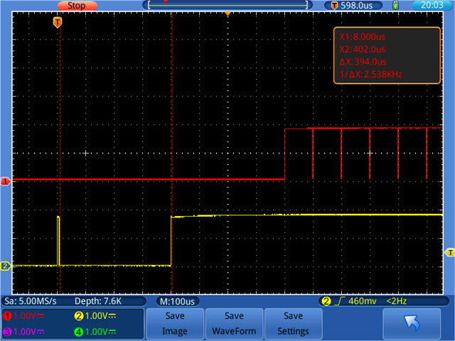
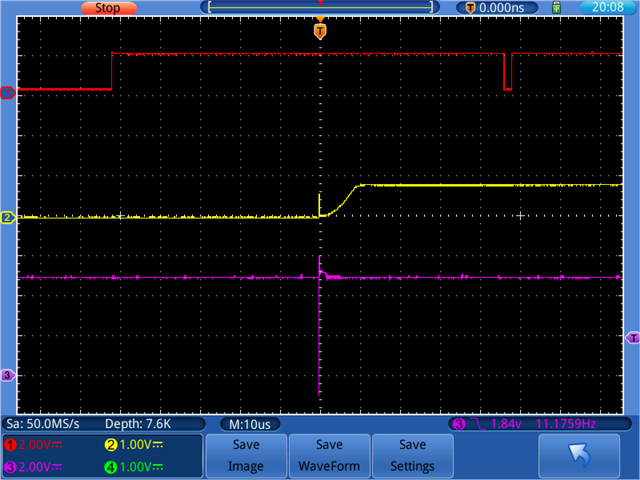
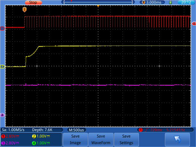
    Waveform taken

    1) Transition from soft start to analog mode (duty 90% or more)
    1 ADIM 2EN

    2) First pulse of SW
    1 ADIM 2 COMP 3 SW

    3) Expanding the first pulse of SW
    1 ADIM 2 COMP 3 SW

    4) SW is not output after the first SW pulse
    1 ADIM 2 COMP 3 SW

    2) to 4), EN is always at H level.

    Please let me know if there are any other waveforms I should look at.

  • Hi Teruyuki,

    Thanks for the waveform. Could you provide more waveforms?

    • No need for probing the EN/PWM and ADIM/HD pin.
    • Only need to probe the SW, COMP and FAULT.
    • Use SW as trigger source and set the sample rate of the oscilloscope as high as possible. (Is there repeated switching between a long interval? Does the FAULT continuously show low voltage level?)

    Best Regards,

    Steven

  • Dear Steven Li

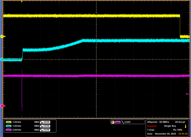
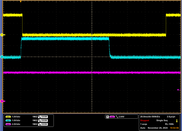
     Additional waveforms

    I changed the oscilloscope to maximize the samples.

    1 FAULT  2 COMP  3 SW

    Currently, the light stays on for 100 ms.
    During that time, if a FAULT occurs, the FAULT is cleared a while after EN is released.

  • Dear Steven Li

    I'm very sorry for the trouble.
    It's been resolved.

    The cause was the FSET pin.
    The circuit diagram was correct, but there was a problem with the implementation, so the FSET pin was open.

    Thank you for your kind support.

  • Hi Teruyuki,

    You are welcome. The FSET pin cannot be left floating.

    I am going to close this thread. Please feel free to contact me again if you have any further question.

    Best Regards,

    Steven