Other Parts Discussed in Thread: UCC28951,
Tool/software:
Hi team,
I have some questions.
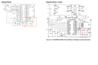
1. Whereas the circuit in the data sheet is a voltage divider from CS The application note is a partial pressure from VREF. Which is correct?

This thread has been locked.
If you have a related question, please click the "Ask a related question" button in the top right corner. The newly created question will be automatically linked to this question.
Tool/software:
Hi team,
I have some questions.
1. Whereas the circuit in the data sheet is a voltage divider from CS The application note is a partial pressure from VREF. Which is correct?

Hi Hirotsugu San,
Please allow me a day to respond on this.
Regards
Hemanth
Hi Hirotsugu San,
Thanks for your patience.
Due to Thanksgiving holiday, we are currently running with limited bandwidth. So, I couldn't get back to you with our response yet.
Please allow me a day more to get back to you.
Regards
Hemanth
Hirotsugu-San,
1. Both are correct. For adaptive delay, connect the ADEL, ADELEF dividers to CS pin; for fixed delays connect ADEL, ADELEF dividers between VREF and GND as explained in datasheet.
2. tABSET expressed in terms of resonant frequency (equation 128 in app note) is to represent the maximum delay time to be set. This is an initial value as mentioned in the app note. tABSET in equation 3 of datasheet is actually used to calculate RAB from an initial value of tABSET .
3. RDELAB is referred as RAB in datasheet. RAB can be calculated from equation 3 in datasheet, for a given tABSET. You just need re-adjust the equation.
4. As mentioned in the datasheet, after the equation (8), various propagation delays and response time delays in power circuit modify the actual pulse width. The initial formula is mentioned int he datasheet. The adjusted empirical formula is mentioned in the application note.
As referred in datasheet - select RTMIN based on observed data and iteration process on a given board.

5. RTMIN minimum and maximum values are as mentioned in the figure 6-7 in datasheet (10kohm to 140kohm). Accordingly the TMIN would be achieved.
6. Connect RSUM to GND for Peak Current Mode Control (PCMC). Connect RSUM to VREF for voltage mode control (VMC). Equation (13) and equation (14) provides the RSUM values by reverse calculating for PCMC and VMC respectively.
Please refer literature for understanding the requirement and amount of slope required for your application.
It is a good idea to read the UCC28950 / UCC28951 datasheet in full as you design the converter using UCC28950 / UCC28951.
Click on "Ask a new question" if you have more questions. Click on "Ask a related question", if you have any specific question related to the thread.
Thanks for considering TI products.
Regards
Hemanth