Tool/software:
Hello everyone, I would need your help.
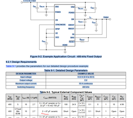
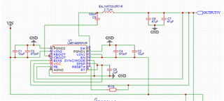
Please take a look at the circuit shematic.
I can't find the error right now.
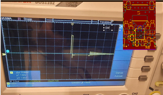
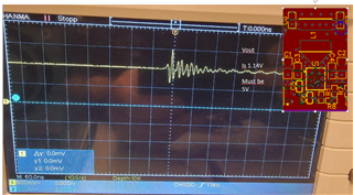
My output voltage is 1.2V.
But it should be 5V fixed.
Thank you for the help :-)
Tool/software:
Hello everyone, I would need your help.
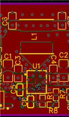
Please take a look at the circuit shematic.
I can't find the error right now.
My output voltage is 1.2V.
But it should be 5V fixed.
Thank you for the help :-)