Tool/software:
We have a circuit configured as below. During charge pump operation, we are seeing a problematic, large current draw into VS. The datasheet suggests 2.7mA, which would prevent proper startup operation on any 12 or 24V system (ours is 36V). This current draw into VS is so large, the drop across the suggested 10K R1 pullup reduces Vvs near zero (Vvs hovers around the Power On Reset voltage of the chip because the chip is oscillating on/off).
Once HGate (Q1) starts to turn on, D2 supplies current to VS and limits how far Vvs can be pulled down, but you can see while the chip attempts to startup the charge pump pulls a lot of current.
This voltage drop to VS means sometimes the CAP charge is not enough to turn on the Q1, and the CAP-VS voltage dips, resetting the HGate driver repeatedly, sometimes preventing startup indefinitely.
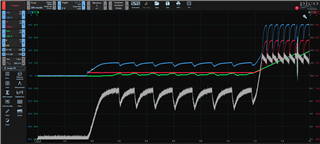
The Q1 on/off oscillation, and then the large current draw (and associated Vvs voltage drop) during charge pump operation, is visible in the below plot.
Due the quantity of parallel FETs required to handle the current in our circuit, our charge pump capacitor is about 2x Cvs.
Why does the charge pump pull this large current, or why is R1 so large (R1 is 10K on the evaluation board design as well)?
Thanks
Thanks


