This thread has been locked.

If you have a related question, please click the "Ask a related question" button in the top right corner. The newly created question will be automatically linked to this question.

TPS25751: PRSwap fails to complete on TPS25751+BQ25756

Part Number: TPS25751
Other Parts Discussed in Thread: BQ25756, PMP41062, , , BQ25756EVM

Tool/software:

Hi,

We are developing a DR battery charger based on TPS25751+BQ25756, similar to PMP41062 reference design.

The port fails to complete a Power Role Swap from sink to source. We have observed the same behavior with TPS25751EVM + BQ25756EVM.

It seems that the problem is that, when the new source needs to power-up the bus, the BQ25756 is never enabled.

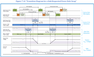
The next figure shows the process of the PRSwap.

Leyend:

- Yellow: bus voltage

- Blue: REGN pin of the BQ25756 (as indicator if the BQ is enabled or not)

- Red: a GPIO of the TPS25751 associated with the enablesource_port1(73) event (as indicator if the port is as source or not). Active low.

- Green: one of the mosfet gates of the buck-boost charger

T1-T2: our device is the sink (enablesource=inactive). The paired device is providing 5V on the bus with an implicit contract

T2: a 20V explicit contract is negotiated and the paired device rises the bus to 20V

T3: our device's buck-boost is enabled (REGN=5V) and sinks current from bus

T4: the PRSwap command is issued, so our device stops the buck-boost (REGN dropping) to stop sinking current.

T4-T5: the paired device stops suppling the bus. The bus voltage drops to cero

(up to here, we believe the process is normal)

T5: our device changes its PR from sink to souce (enablesource becomes active)

T5-T6: the REGN never gets 5V again, so it seems the buck-boost is not enabled, and our device, as source, cannot mantain the bus at 5V and the port is detached.

This was with the 5V PDO sourcing from PP3. We tried changing it to PP1, and the result was that at T5-T6, our device sources correctly 5V to the bus from that PP1, but when a new PDO is negotiated, it fails to change to the new bus voltage from PP3 as the buck-boost is not enabled (REGN is low).

The next figure shows the exchanged PD messages:

This is our configuration file:

Configuration_PRStoSource_TI.zip

Any idea why this is happening?

Thanks in advance

  • Hi Igor, 

    Thank you for reaching out!

    Could you provide details on your test setup? Are you testing with a real battery or battery simulator?

    I will review and provide feedback early next week. 

    Best Regards, 

    Aya Khedr 

  • Hi Aya,

    Thanks for the reply.

    The setup consists of:

    - Our PCB based on TPS25751+BQ25756, configured as DRP with Try.SRC and "initiate Swap to source = ON", connected to a bidirectional power supply (it is not a battery emulator but it can source and sink current like a battery does). 

    - As port partner TPS25751EVM+BQ25756EVM, configured as DRP with Try.SRC and "process Swap to sink = ON", connected to a power supply in parallel with an electronic load.

    Result: as both devices are DRP with Try.SRC the initial role assignation seems arbitrary. When our device connects as source it stays as source and works fine. When our device connects as sink, it initiates a PRSwap to source that fails as explained above.

  • Hi,

    Please expect delay in response due to Thanksgiving holiday.

    Regards

  • Hi Igor, 

    Thank you for clarifying. What is the port's role of the PCB in the PD logs provided above? (I am assuming sink in this case?)

    Could you provide some insight as to why the boards are configured with "Try.SRC"? See the below recommendations for the Try.SRC implementation from the Type-C spec: 

    Could you also provide the json used for the port partner? I will replicate on my end and get back to you with feedback. 

    Best Regards, 

    Aya Khedr 

  • Hi Aya,

    For the sake of clarity, let’s call:

    • OUR_PORT to our designed PCB based on TPS25751 and BQ25756 in autonomous operation (no MCU intervention)
    • TI_EVM_PORT to the port partner based on TPS25751EVM and BQ25756EVM

    1) Could you provide some insight as to why the boards are configured with "Try.SRC"?

    OUR_PORT needs to be UFP for data, and DRP with source preference for Power. We were giving preference to the power role, which is not the recommendation of the PD standard according to the table you linked. We need to review this.

    Regardless of this, we wanted OUR_PORT to be connected as sink and force a PRSwap. As OUR_PORT was configured as DRP with Try.SRC, the solution we found was to configure also TI_EVM_PORT as DRP with Try.SRC. To force the PRSwap we configured in OUR_PORT “initiate PRSwap to Source=ON” and in the TI_EVM_PORT “process PRSwap to Sink=ON”.

    We believe the problem could also be replicated with OUR_PORT as DRP with Try.SNK or no preference and "initiate PRSwap to Source=ON", and the TI_EVM_PORT as DRP with source preference, as what is failing is the PRSwap.

    2) What is the port's role of the PCB in the PD logs provided above? (I am assuming sink in this case?)

    OUR_PORT is a DRP with Try.SRC that has connected as sink. The TI_EVM_PORT has connected as source. OUR_PORT initiates a PRSwap to Source.

    I will explain what we see on the PD logs, in case it helps:

    And compare them to the process of a Sink Requested Power Role Swap of the standard (figure 7.41):

    OUR_PORT initially connects as Sink.

    Messages 514 and 516 are 5Amp cable validation

    Messages 518 to 521: TI_EVM_PORT (source) sends its source capabilities

    Message 523: OUR_PORT (sink) requests the 20V/5A PDO

    Message 525: TI_EVM_PORT (source) accepts the request

    Message 527: TI_EVM_PORT (source) informs that the 20V/5A PDO is ready

    Messages 529 and 531: are not relevant for the problem we are analyzing, but it is TI_EVM_PORT requesting a DRSwap and OUR_PORT rejecting it.

    Message 533: OUR_PORT (sink) requests a PRSwap

    Message 535: TI_EVM_PORT (source) accepts the PRSwap (step 1 on figure 7.41)

    Message 537: TI_EVM_PORT decreases the bus voltage to 0V (step 4), switches its Rp to Rd to become sink and sends PR_RDY (step 5) to OUR_PORT

    Message 539: we believe OUR_PORT receives the PR_RDY and switches its Rd to Rp to become source (as we see enablesource_port1(73) event is activated), but it fails raising up the bus voltage to 5V (step 7). Regardless of this, it sends the PR_RDY (step 8) to the TI_EVM_PORT, but the bus is not ready, and the ports detach.

    3) Could you also provide the json used for the port partner?

    This is the json for the TI_EVM_PORT

    7762.Configuración_PRStoSource_EvaluationBoard_TI.zip

  • Hi Igor, 

    Thank you for the detailed response. 

    I will replicate and get back to you with feedback by Thursday. 

    Best Regards, 

    Aya Khedr

  • Hi Aya,

    Any update on this? did you manage to replicate the error?

    Thanks!!

  • Hi Igor, 

    Apologies on the delay here. I will have some feedback for you by end of week. 

    Best Regards, 

    Aya Khedr

  • Hello Aya,

    Excuse me for insisting but it's been 3 weeks since the first post and we would really appreciate your help.

    Have you tried to replicate the error? We have replicated the error both on our desing and on the evaluation boards.

    It looks to us it is some kind of problem with the TPS25751 ¿firmware? not enabling the BQ25756 when the role changes from sink to source, as we dont see any configuration parameter related to this.

    Thanks in advance

  • Hi Igor, 

    Thank you for your patience. 

    I am working on replicating your setup with the provided jsons using two sets of EVMs. 

    I was able to see a successful power role swap when the board flashed with your "OUR_PORT" configuration starts as a Source but have not evaluated it starting as a Sink just yet. 

    In the meantime, do you have I2C logs of the PD+BQ communication in the case where your device initiates the power role swap? 

    Best Regards, 

    Aya Khedr 

  • Thanks for your feedback Aya

    If I'm not misunderstanding you have performed a PRSwap from Source to Sink in one set of EVM, implying a PRSwap from Sink to Source in the other set of EVM. Can you send us the configuration file you used in the EVM that is Swaping from Sink to Source. (We also had tested PRSwap from source to sink successfully in our device, but had to do it with another port partner, because when we tested with the EVMs as port partner, the EVMs failed to Swamp from Sink to Source). 

    We don’t have I2C logs so far, but I'll try to log them.

    We also noticed there has been an update on the USBCPD_APPLICATION-CUSTOMIZATION-TOOL from the 0.6.0 we are currently using, to a newer 1.0.2. Could this be affect? does this tool flash only the configuration or also the firmware TPS25751?

  • Hi Igor, 

    Yes, please use the latest GUI and generate a new json based on your configuration settings (i.e. do not import previous json file). There are updates made in v1.0.2 that may have improved the PRS behavior from v0.6.0. 

    Could you please retest using the latest and let me know if you still observe the same behavior?

    Best Regards, 

    Aya Khedr 

  • Hello Aya,

    Sorry for the late response. We've being testing and the upgrade from v0.6.0 to v1.0.2 solved the problem on the PRSwap from sink to source that looked like the TPS25751 was not enabling the BQ25756 after the PRSwap.

    Thank you very much for your support.

    Igor.