LM5013-Q1: Current Assumption with 5V output

Part Number: LM5013-Q1

Tool/software:

Hi Expert,

Customer is considering lm5013-Q1. They have concern about power assumption. They require the current assumption of lm5013-Q1 is lower than 30uA when the 5V output keep. 
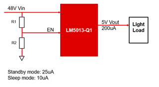
Question 1: when lm5013-Q1 is in sleep mode, the light load still needs input voltage, the 5V output is still exit?

Question 2: when lm5013-Q1 is in standby mode, the light load still needs input voltage, the 5V output is still exit?  Because I see internal controller circuits are turned off in standby mode or sleep mode.

Question 3: How to enter light mode? The work mode is controlled by resistor divider (R1 R2).

If the assumption is not available, can you give a solution to achieve the low current assumption target?

  • Hi Beida,

    Question 1: when lm5013-Q1 is in sleep mode, the light load still needs input voltage, the 5V output is still exit?

    <Nitya>: Yes, the output voltage still exists in this mode. The explanation for sleep mode is as follows. 

    "During discontinuous conduction mode, the load current is lower than half of the peak-to-peak inductor current ripple and the switching frequency decreases when the load is further decreased in pulse skipping mode. A switching pulse is set when VFB drops below 1.2 V.

    As the frequency of operation decreases and VFB remains above 1.2 V (VREF) with the output capacitor sourcing the load current for greater than 15 µs, the converter enters an ultra-low IQ sleep mode to prevent draining the input power supply. The input quiescent current (IQ) required by the LM5013-Q1 decreases to 10 µA in sleep mode, improving the light-load efficiency of the regulator. In this mode, all internal controller circuits are turned off to ensure very low current consumption by the device. Such low IQ renders the LM5013-Q1 as the best option to extend operating lifetime for off-battery applications. The FB comparator and internal bias rail are active to detect when the FB voltage drops below the internal reference, VREF, and the converter transitions out of sleep mode into active mode. There is a 9-µs wake-up delay from sleep to active states." 

    Question 2: when lm5013-Q1 is in standby mode, the light load still needs input voltage, the 5V output is still exit?  Because I see internal controller circuits are turned off in standby mode or sleep mode.

    <Nitya> : The device is in standby mode when EN/UVLO is greater than 1.1V but less than 1.5V(typical). In this mode; the output voltage is disabled. The normal mode(active mode) is enabled as soon as EN_UVLO voltage is greater than 1.5V. 

    Question 3: How to enter light mode? The work mode is controlled by resistor divider (R1 R2).

    <Nitya> : Device enters into different modes depending upon the load current. 

    Thanks,

    Nitya

  • Hi Nity,

    Thanks for your strong support. For the FB voltage range is 1.181V~1.218V,  the 5V output is accordingly 4.92V~5.075V. So the output accuracy is 8%. Do I calculate correctly?

    Customer's requirement accuracy is lower than 1.5%. Whether it means that the LM5013-Q1 can't meet the accuracy requirement?

  • Hi Beida,

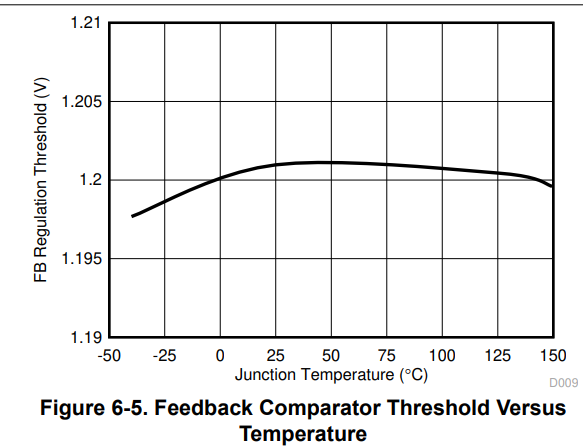
    The feedback voltage 1.181V is at -40C and 1.218V at around 50C. Across the temp range of -40C to +25C and from +25C to +150C; the feedback voltage accuracy is 1.5% as shown below for LM5013-Q1 device. However across -40C to +150C the FB accuracy is 3% [ min to max]. This should not be a problem for customers

    Thanks,

    Nitya

  • Nitya,

    In the figure, the FB threshold is 1.197V at -40C and 1.203V at 50C, which is not matched with 1.181V and 1.218V. I am confused how do we get the value of 1.181V & 1.218V?

  • Hi Beida,

    Sorry for the confusion here.

    The Feedback voltage is trimmed to 1.2V[typ] and min and max values are 1.181V and 1.218V. and across the temperature the 1.2V can vary depending upon the graph shared above.

    Hope it is clear now.

    Thanks,

    Nitya

  • Hi Nity,

    Thanks for your support.  It's clear now. In my view, our some devices FB is 1.181V, and some one is 1.218V. It's a trimmed probabilistic events. Overall materials, the FB range is 1.181V ~1.218V. Thus. the voltage accuracy error 8% is not avoid. Is my view correct?

    Another new question:

    I test the lm5013-Q1 in Webench. The input is 48V and output is 5V, load current is 0.5A. The efficiency is 85.7%. Do you have suggestions to improve efficiency to 90%+?

  • Hi Beida,

    Regarding first point about the FB accuracy; your under standing is correct. 

    Regarding efficiency; Recommend you use better DCR value resistance inductor value and lower forward drop async diode.

    Thanks,

    Nitya

  • Hi Nity, 

    Understood. Thanks a lot.