Tool/software:
Hello.
I made a PCB with the TPS23753A PoE controller. The design is mainly based on the reference design of the TPS23753AEVM-001 (5V output) board. I changed the transformer because of availability and used one from Wuerth 749119950 with similar specs.
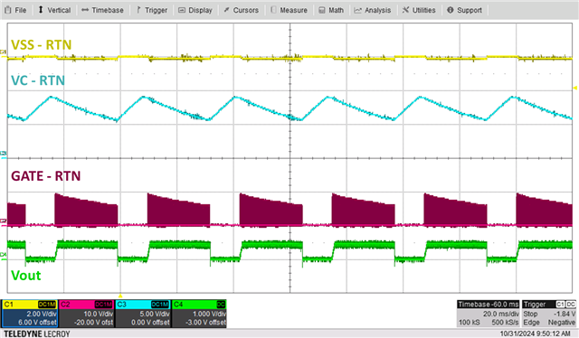
Basically it is working. But at the startup I have a strange behavior. When I connect the PSE the output is regulated very well to the nominal 5V output. But after a few milliseconds (40 to 50ms), the the switching stops and the output voltage is falling. Is this because of light load and the discontinuous mode? Please have a look at the picture below. CH3 is the output voltage and CH4 is the gate output to the Mosfet.

Another strange thing I observed is, that during the first 40-50ms when the switching looks good, the voltage between RTN and VSS is rising. Looks like the hotswap Mosfet would be switched off? Below is the waveform of the output voltage (CH3) and the RTN-VSS voltage (CH4). Shouldn't the voltage between RTN and VSS be close to 0V?

The PoE power supply is powering a CPU module. When the CPU module is booting up, the PoE voltage becomes stable and stays pretty well at 5V. Even with the CPU board, I have a few hundreds of milliseconds before the output voltage becomes stable. So, I'm not sure if this "issue" is because of light load at the beginning or there is a more serious issue?!
Thanks,
Andreas