This thread has been locked.

If you have a related question, please click the "Ask a related question" button in the top right corner. The newly created question will be automatically linked to this question.

TPS25751: CC Configuration

Part Number: TPS25751

Tool/software:

Hello,

Its mentioned everywhere using USB PD- UFP and DFP is based on the  RP and RP on CC pins. Do we need to add an option for external Pull up and external Pull down on the CC lines ?. This is not given in the EVM schematics or application schematics. Or are they internally configured using the GUI. By any chance will adding an external RP and RP (DNP) helps ?

Thanks.

  • Hi Sobin,

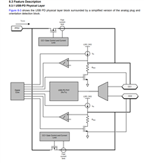
    The TPS25751 provides the CC line terminations. They are configured in the GUI when you choose the operating power and data roles. By default, a non-powered PD controller will expose the RD resistors on the CC lines to enable a "dead battery" boot. Allowing a far end to provide power and the TPS25571 to boot from an VBUS powered state.

    See the block diagram from the datasheet shown below.

    You do not need to add RP and RD resistors.

    Thanks and Regards,

    Chris