BQ77915: Load Current is not increasing with Current Resistors Changes

Part Number: BQ77915
Other Parts Discussed in Thread: UCC27517, BQ77307, BQ76922

Tool/software:

Hi Team,

We have developed 12V BMS using BQ7791506 for 40AH Starter Battery in Vehicle. But during Cranking, the BMS is not allowing required Cranking Current. So that we tried to change current resistors ( presently 1mohm in 3 parallel R17, R18, R19) by adding more current resistors. But current is not increasing. The required Cranking Current is approximately 400A+. Discharge Gate Resistors are R21 -10K and R23-R27 - 130E and Charge Resistors are R37-4.7K and R32-R36 - 130E. I have attached the MOSFET (TO-263)  datasheets and Schematic. So please check and give the suggestions to resolve this issue.

Thanks,

Jaya PrasadSPN04200.pdf40AH BMS Schematic.pdf

  • Hello Jaya,

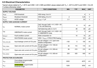
    Your current sense resistor sounds too high. You mention three 1-mOhm resistors in parallel, so ~0.333-mOhm. If you need discharges above 400-A with the BQ7791506, you require a maximum resistance of 50-mV / 400-A = 0.125-mOhm.

    You also have to take into account the protection's tolerances:

    So for OCD1 in this case, 50-mV +/-10-mV for the protection. You would want to choose your current resistance to account for it.

    Best Regards,

    Luis Hernandez Salomon

  • Hi Luis,

    Thanks for your response and suggestions. But why discharge current increasing with increasing the discharge gate resistor value from 10K to 47K or more? can you please explain about it?

    Thanks,

    Jaya Prasad

  • Hi Luis,

    Please check my gate resistor values in Charge and Discharge and my MOSFET Qg is 235nC. Please give the proper calculation for gate resistors also.

    Thanks,

    Jay

  • Hello Jaya,

    Typical values for the gate resistors is much lower than that. 5-kOhm should be okay. 

    Changing the resistor of the gate should only really affect the turn-on/off of the MOSFETs. The MOSFET itself is what would allow the current flow, the BQ77915 does not affect the current flow and will only turn the MOSFETs ON or OFF.

    Best Regards,

    Luis Hernandez Salomon

  • Hi Luis,

    Thanks for your response and I have one doubt. I thought of that my MOSFETs are not switching properly because MOSFET Qg=235nC and it requires higher gate drive current from IC. Even I increasing the number of current sense resistors, the discharge current not increasing and observed DSG drive signal is going to off.

    Can I use Gate Driver (UCC27517) for CHG & DSG pins without driving directly from IC? if possible please show how to use?

    Thanks,
    Jaya Prasad

  • Hello Jaya,

    I do not believe that 235nC should cause this problem. Typically that would cause the FETs to be slower in their switching speed, but it should still drive to an appopriate level. For your case, what are the voltages seen on the DSG/CHG pins with respect to Vss?

    You could use a gate driver if desired, but I'd think it should not be necessary. We have used the UCC27524DR in other devices for low-side FET drivers.

    Best Regards,

    Luis Hernandez Salomon

  • Hi Luis,

    Thanks for reply and I have observed Voltages with respect to Vss at DSG/CHG pins are 12V. So please suggest me the gate resistors to drive at 400A current and already using current resistors 0.12mohms but discharge current not increasing with current resistors decreasing. It's only increasing with gate resistor increasing. This means switching speed will be slow and MOSFETs will fail during fault conditions. So please help me to resolve this issue.

    Thanks,

    Jaya Prasad

  • Hello Jaya,

    What is the voltage with the higher gate resistance? What is the voltage drop across the MOSFETs (drain-source) during this test?

    At 12V, the MOSFETs should be fully enhanced/ON. Changing gate resistance should not really be affecting the current flow at this stage, as this is a capacitive component, so once it is ON, it will draw only leakage currents. 

    Best Regards,

    Luis Hernandez Salomon

  • Hi Luis,

    The problem of current sensing was resolved by removing 100E resistors and shorted. I have one more issue is Under Voltage protection disable. So how to disable Under Voltage protection in BQ7791506? Please suggest me the modifications or suitable IC.

    Thanks,

    Jaya Prasad

  • Hello Jaya,

    The engineer is currently Out of Office for today and tomorrow. They will be back Monday to provide a response.

    Thank you for your patience.

    Best Regards,
    Alexis

  • Hello Jaya,

    Interesting. What resistors did you remove?

    UV cannot be disabled from this device. If you would like a device that can disable UV, you could use the BQ77307 instead, which is a programmable protector, so UV could be disabled if needed. 

    Another IC that could be used, would be the BQ76922, which is a monitor and protector device that can be OTP'd with your custom settings and work standalone.

    Best Regards,

    Luis Hernandez Salomon

  • Hi Luis,

    Thanks for your response. I have removed the 100E resistors (SRN & SRP) from current sense resistors.

    Can I use BQ77307 without MCU and for 300AH Battery. 

    How to disable UV in this IC and can you please share any reference circuit?

    Thanks,

    Jaya Prasad

  • Hi Luis,

    How to program Undervoltage in BQ7791506 for lower voltage like 1.2V.

    Thanks,

    Jaya Prasad

  • Hi,

    The engineer will be out for winter holidays until the New Year.

    Thank you for your patience.

  • Hello Jaya,

    The protections are programmed at the TI factory before shipping out. In order to create a new device with custom settings, a new spin would have to be made. 

    The BQ77307 requires an MCU in order to program the thresholds, as it does not have customer OTP to program custom settings.

    The BQ76922 however, does have customer OTP, so you could program your custom settings to it, although this would require an additional production flow, as to program the OTP, 11V is required on VC5/BAT.

    Best Regards,

    Luis Hernandez Salomon

  • Hi Luis,

    I am asking about BQ77915 regarding Undervoltage and in datasheet given as minimum is 1.2V and written as programmable. Is possible to set at 1.2V. So please clarify this.

    Thanks,

    Jaya Prasad

  • Hello Jaya,

    As I clarified in my previous reply:

    The protections are programmed at the TI factory before shipping out.

    Meaning, this can only be programmed by TI. See Section 6 Device Comparison Table of the datasheet for reference of currently released devices.

    Best Regards,

    Luis Hernandez Salomon

  • Hi Luis,

    Thanks for clarification on undervoltage settings. So can you please suggest the device which IC suitable for my application means with undervoltage settings of 1.2V-1.5V with / without mcu requirement. 

    My application is 12V BMS / 300A  with undervoltage cutoff at 10V (without Load Removal option). BQ7791506 / BQ77307 ar not fulfil my requirements.

    Thanks,

    Jaya Prasad

  • Hello Jaya,

    See my previous response:

    The BQ77307 requires an MCU in order to program the thresholds, as it does not have customer OTP to program custom settings.

    The BQ76922 however, does have customer OTP, so you could program your custom settings to it, although this would require an additional production flow, as to program the OTP, 11V is required on VC5/BAT.

    Best Regards,

    Luis Hernandez Salomon