This thread has been locked.

If you have a related question, please click the "Ask a related question" button in the top right corner. The newly created question will be automatically linked to this question.

TPS65262-2: Seen dip in Buck output

Part Number: TPS65262-2

Tool/software:

Hi Team, 

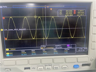
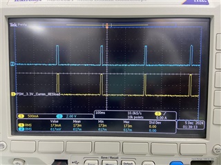
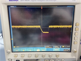
We are using this PMIC IC in our design. And we are seeing a dip in 3.3V which we are taking from BUCK2. 

Input was stable and Current consumption is around 100mA only. But once the board is powered on, 3.3V is reduced to around 1.8V for around 14 to 15mS. 

FCC mode is selected. After booting, This dip is happening more often in irregular time intervals. 

Can you advice me anything to eliminate this issue. 

Thanks in advance.

  • Dear, Sir,

    Thanks for reaching out. Pls kindly let me check and get back to you during these days.

    BRs

    Lucia

  • Hi Lucia

    Thanks for the reply. 

    I would like to add 2 more questions here. 

    1. We have checked this issue further. We probed the current using current probe. And got below attached wave form. 

    But when we set up a resistive load to drain 100mA to 700mA. In this case current was proper in straight line. 

    2. While consuming more than 700mA. image was like this. After this current was 0.


    Can you check and tell me, Where I can check further.

  • Dear Sir,

    Thanks for more information. Yes, I will check and get back to you. Thank you for your patience!

    BRs

    Lucia

  • Dear Sir,

    Could you pls share me your schematic first? And when there is output voltage dip, could you also share me the waveform of LX2 and inductor current?

    1. What is above current waveform represent for? Is it the load current? But why it shows like a sin wave which is strange?

    2. For the last waveform, what does channel 1 and channel 2 represent for? Are they load current and output voltage?

    3. Usually, when we see a voltage dip, you can debug from these perspectives includes: (1) Overcurrent condition, double check if you disconnect the load, and using E-load or resistor load, will you see the issue? (2) Over temperature condition, you can measure the case temperature of the device. But looks like you only see this Vout drop with Buck2, right? Buck1 and Buck3 both operate good. Thus, it likely that the OT is not triggered; (3) Check the loop stability of the device and check whether it's stable. You can measure the LX2 waveform to see if there is unstable pulses. If the loop compensation is not designed good, there will also be possible that you will see Vout drop. Pls check any open/failure/solder defect of these compensation components which are related with the loop performance.

    Thank you!

    BRs

    Lucia

  • Hi Lucia, 

    Thanks for your response. 

    This is our schematics. In this we are seeing a dip in 3.3V (Buck 2 Output). And we found that we are getting dip while giving 5V input to the PMIC. 

    If we are giving 7V voltages are stable. 

    Details,

    5V input to the PMIC: Above dip is coming in Buck 2(3.3V) often. All other voltages are stable.

    7V input to PMIC: All the voltages are stable. No dip issue. 

    Can you suggest me anything to be taken care in my schematics. 

    Looking forward to the fast response. Thanks for understanding. 

  • Dear Sir,

    Thanks for your feedback. Pls give me some time to review the schematic and I will give you feedback by end of this week. Thank you!

    BRs

    Lucia

  • Dear Sir,

    Is there any voltage variation of your input voltage power supply? From your description, 5V is close to the minimum Vin of TPS65262-2 which is 4.5V. I am worries that if there is maybe long wire, the actual input voltage might not be 5V which might cause the device to shut down temporarily. You can measure VIN waveform to double confirm.

    Thank you!

    BRs

    Lucia