This thread has been locked.

If you have a related question, please click the "Ask a related question" button in the top right corner. The newly created question will be automatically linked to this question.

TUSB546A-DCI: TPS65987 & TUSB546 I2C3 Error

Part Number: TUSB546A-DCI
Other Parts Discussed in Thread: TPS55289, TPS65987, TUSB564

Tool/software:

Hello I am experiencing an error on the I2C3 bus after the ACK please see the image below: 

Note that the rising edge of the data is "colliding" with the falling edge of the clock. Also note that TPS55289 is also connected on this bus on address 0x74 and when a command is sent to 0x74 it does not experience this "collision", there is no "error" and the TPS5529 works just fine. However I suspect the TUSB546 on address 0x13, is failing to work because of this i2c error in rise and falling edge of SDA and SCL. As i said both 0x74 and 0x13 devices are on the same bus with the same circuitry, same pullups....with the 0x74 working just fine and the analog signal associated with 0x74 communication looks correct. Please advise. 

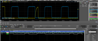
You will also note that SDA takes longer to rise. I was hoped that putting a larger pullup on SDA would help get it over the goal line but to no avail. Attached is my PJT for your reference. 
I am aware of documents SLVAE18. Thank you for your time.
test3_dp.pjt

  • Hi Brent, 

    We have received your inquiry and a team member will assist you shortly. 

    Best Regards, 

    Aya Khedr 

  • Hi Brent,

    I am on the team that supports the TPS65987 PD controller product line. It seems like the thread got assigned to our group, so let us check on some things to confirm the TPS65987 is not an issue. I can reassign the thread to the TUSB team after we have confirmed.

    1. It sounds like there are multiple ics on the bus, the TPS55289 and the TUSB564. The TPS55289 works fine, while the TUSB seems to have some SDA rising edge issues.
      1. Are there any possible issues with layout? Are there any possible issues with the routing?
    2. Do you see this issue on multiple boards? If you swap out the IC for a new one, does the behavior persist?
    3. Does this issue happen with all writes to the TUSB device? Is the behavior consistent to a certain bit of the payload?

    I have not seen issues relating to the I2C communications in this regard, so am wondering if there are any concerns with the layout specific to the TUSB team. In my experience using EVMs and boards with these parts, I have not seen any issues like this in the past.

    What value pullup are you using and what bus are you pulling it up to? Are you using LDO3V3? Does LDO3V3 have sufficient capacitance.

    Thanks and Regards,
    Chris

  • Hi Chris, slightly separate question but on the topic of the LDOs. If we have a system with a removed battery but we would like to power the system with 20V from VBUS, as I understand it, PP_CABLE may need to be supplied with 2.8-5V in order to complete the 20V PDO request. Is it possible to power PP_CABLE with the LDO3V3? Or do we need an external LDO to drop down VBUS to 5V? Thank you. I will get 

    On I2C pullup, yes we are using LDO3V3 for pullup. I am currently using a 2.3K pullup on the SDA and 500 ohm on the SCL. We had 3.3k pullups on these and I had been playing with various values to get the TUSB to work, these are just arbitrary values that I arrived at trying to test various setups. Just a reminder the TPS55289 works just fine with the 3.3k pullups and the 2.3k/500

    1) a. It is possible but not likely. The routing issue that might be problematic is that the master is physically located in between the two slaves instead of daisy chaining the slaves. 

    2) I have not tried swapping out the device or trying another board. I will try and get back to you. 

    3) This happens with all writes after the TUSB device address 0x13 returns with ACK there is an error. I will check again 

  • Hi Brent,

    No, do not power PP_Cable from LDO3V3.

    Usage of PP_CABLE depends on your expected use case and role. The purpose of PP_CABLE is to provide VCONN, or cable power when required. VCONN powers circuitry in the cable and allows the cable to respond to PD messaging. There are two common cases where this is needed. In general, it is required if you need to communicate with the cable. If you do not need these, you can leave it floating. If you do, we typically want a dedicated 5-V source.

    1: PD controller acting as source wanting to provide more than 3-A. To be able to negotiate a PD contract with >3-A, the cable needs to support it. To make sure the cable supports it, the Source must query the cable to determine it's current carrying capability, which means VCONN is required.

    2. DFP/UFP wants to discover cable capabilities. For some higher speed communications (USB4, TBT), the cable needs to be queried to determine cable speeds before negotiating one of these communication protocols. This is typically done by the "Host" or DFP end.

    So if you have these requirements, you may need PP_CABLE and would need a 5-V rail. Typically these requirements would come from a system with internal power, that is not powered off of VBUS.

    If you don't, you may be fine leaving the pin floating.

    I'm going to reassign this thread to the TUSB564 team so they can help look into the I2C issues as it does not sound like a PD issue. I'll continue to monitor this thread if you have more PD questions. If you have PD questions unrelated to this post, go ahead and create a new thread for the specific issue and we can provide support their.

    Thanks and Regards,

    Chris

  • Hi Brent,

    I'm on the team that supports our TUSB parts. Can you share the schematic of the TUSB546 implementation?

    Also double check that the device is in I2C mode by pulling I2C_EN to 3.3V

    Best,

    Shane

  • Hi Chris

    thabk you for the prompt response. What about no system 3.3v. From how i understood the datasheet, the device is supposed to power up from VBUS but it is not able to to complete 20V negotiation w out 3.3 input externally from the system. 

    you da man Chris ty!

  • Hi Brent,

    The device can act as power up from VBUS with no system 3.3V as you mentioned. When we get power from VBUS, we will provide power on LDO3V3 which can provide power to the SPI flash. With this in place, the PD controller can boot and load an image from the SPI Flash. In this configuration, we really only support acting as a sink, and will be able to negotiate 20-V sink contracts with no issue. One thing to note is that if we boot from VBUS, we call this booting in "dead battery" and a field call the "dead battery flag" is set. While this is set, the PD controller can only source a 5V default type-c contract (if sourcing at all).

    Also, the different "dead battery configs" (see datasheet) will affect how the PD controller can negotiate initial contracts while in dead battery.

    For SPI flash applications, we typically recommend BP_NoWait.

    Also see Shane's request above. He should be able to help more with the I2C issues you are seeing.

    If you have more PD specific questions, can you open another thread with just the TPS65987 as the device? It will make issue tracking easier. Feel free to reference this thread.

    Thanks and Regards,

    Chris

  • Hi Shane, 

    Do you have any comment on the Detach trigger for the mux in the .pjt that I sent, does this look correct? 


    Yes I2C_EN is pulled high through a 1K.

    What is your email Shane?

    Thank you. 

    Brent

  • Hi Brent,

    Do you have any comment on the Detach trigger for the mux in the .pjt that I sent, does this look correct? 

    What is the purpose for this detach trigger? Whether it is correct is a better question for Chris as I do not support the PD controller customization tool.

    What is your email Shane?

    Its our group's policy to keep support on E2E rather than go through email for better team tracking. If you'd like to private message the schematic, please accept my friend request and use the direct message feature on E2E. This will create a separate space that is only viewable to you and myself.

    Best,

    Shane

  • The detach trigger disables the MUX. It's the same setup as in the slvaem6 application note:
    https://www.ti.com/lit/an/slvaem6/slvaem6.pdf?ts=1733974865856
    See page 12. 

    Actually maybe you can find this out, is Figure 2-20 a typo? It says "Detatch" but maybe it should say "Hard Reset". Figure 2-19 already describes Detach trigger in its entirety?

  • Hi Brent,

    You are correct that Figure 2-19 describes the Detach trigger. What you have in your image looks correct to disable the MUX. Figure 2-20 shows how to disable AUX snooping, however this would be redundant if you are already disabling the USB and DisplayPort lanes as shown in Figure 2-19.

    For the I2C bus, I see you're using 3.32K pullups on SDA and SCL. Can you try reducing the value on these resistors to 2K? Our TUSB546A datasheet specs these resistors at 2.2K maximum if operating at 400kHz 

    I would also check that there is no large capacitance on the I2C SDA Bus. The slow rise time shown in your image could be due to a large capacitance on the line or a weak pullup.

    Best,

    Shane

  • Hi Shane I've tried reducing the pullups and decreasing bus capacitance but I'll do some experiments again and report back.

    I have a question on the max input of the I2C pins when the device is unpowered i.e. Vcc = 0, does the following still hold:

    If the I2c inputs were tolerant of 3.3V while Vcc = 0 then we could unpower this device when the system is off and TPS6598 is on supplied by VBUS

    Thank you Shane
    Brent

  • Hi Brent,

    The SDA and SCL pins (CTL0 and FLIP) are failsafe so it is ok to have 3.3V on these pins while VCC = 0:

    Just to confirm, are you able to read and write to the TUSB546 correctly? I'm curious if the I2C works functionally even though you see this behavior on the falling edge of SCL.

    I see this occurs right after the I2C 'Ack' from our device. Can you show the waveform during a read or write to the TUSB546 as well for comparison?

    Best,

    Shane