This thread has been locked.

If you have a related question, please click the "Ask a related question" button in the top right corner. The newly created question will be automatically linked to this question.

TPS92620-Q1: Would like to calculate the power dissipation

Part Number: TPS92620-Q1

Tool/software:

Hi team,

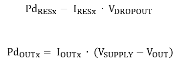
My customer would like to estimate the junction temperature at the specific use case. Could you please check if my understanding below is correct to calculate the power dissipation of TPS92620-Q1?

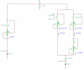
When the circuit is Figure 7-4, 

V(SUPPLY) = 12V (typical)
V(OUTx) is typical 2 × 2.2V = 4.4V.
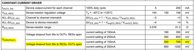
I(OUTx_Tot) = 130mA (maximum)

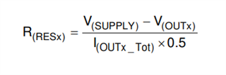
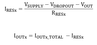
(12V - 4.4V) x 130mA = 0.988W.
so power dissipation in TPS92620-Q1 is 0.988W.
Is my understanding correct?

Best regards,
Shunsuke Yamamoto
  • Hi Shunsuke-san,

    I've created a simplified model in TINA-TI to help understand power dissipation in LED drivers with external thermal sharing resistors.

    The path on the left represents TPS92620-Q1 without external thermal sharing (OUTx connected to RESx). The internal power dissipation is 988mW as you calculated.

    The path on the right represents TPS92620-Q1 with external thermal sharing resistors as determined by equation 9 in the datasheet. The power dissipation in the OUTx channel (PM3) is 520.3mW and the RESx channel (PM4) is 24.6mW, for a total internal power dissipation of 545mW. The power dissipation in the 117Ω external R(resx) resistor is 443mW.

    In both cases, the total power dissipation is 998mW. However, the R(resx) resistor dissipates power outside of the TPS92620-Q1 which helps reduce the junction temperature of the device at high loads.

    TPS92620-Q1 Power Dissipation.TSC

    I've attached the TINA simulation for your reference.

    Regards,

    Zach

  • Hi Zach-san,

    Thank you for your clear explanation. but I have a question. 

    1. How did you calculate the value of 520.3mW and 24.6mW?

    Best regards,

    Shunsuke Yamamoto

  • Hi Shunsuke-san, 

    The TPS92620-Q1 thermal sharing operation works by applying as much current as possible through the RESx pin, and the remaining current through the OUTx pin. This means that the RESx pin operates at the dropout voltage of the internal constant-current regulator.

    The exact dropout voltage depends on the operating conditions and varies from part-to-part. For this example I selected 400mV as a reasonable value.

    The current through the RESx and OUTx pins can be determined by the following equations:

    Once the current is known, the internal power dissipation for each output can be determined by the following equations:

    Regards,

    Zach