This thread has been locked.

If you have a related question, please click the "Ask a related question" button in the top right corner. The newly created question will be automatically linked to this question.

UCC28061: UCC28061 optimize or Update to 28065?

Part Number: UCC28061
Other Parts Discussed in Thread: UCC28064A, UCC28065, UCC28063

Tool/software:

Hi,

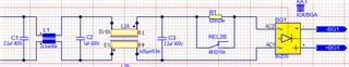
i started in a new company and reconized, that one of our powersources including 28061 has a poor PF 0,44-0,48 when running without load.


Unfortunately the expert died due to cancer, before he made a dokumentation of his working process.

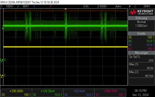
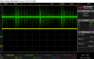
I decided to update it to a later version and tried to rebuild the pcb by hand. I tried 28064 from demoboard with 260uH and 28065 with sluc645c with 260uH. All versions came out with ~310V without switching.Abgestimmt sluc645c.xlsx

Is it possible to improve the 28061 ?

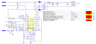
We have a tiny space for the pfc, how can i make use of the smaller inductors with the 28065 chip?

Regards Sascha

  • Hello Sascha, 

    On your first issue:
    Any PFC converter, whether using UCC28061 or any other controller, will have very low PF when the PFC has no load. 
    This occurs because of the X-Caps in the EMI-filter.  With no load after the bridge rectifier, you simply have capacitors across the AC line, which cause leading AC current.
    I am surprised that the PF is even as high as 0.44 under no-load conditions. 

    On replacement with UCC28064A or -065: 
    TI has no plans to revise the UCC28061 to an "improved" version, so for smaller inductors it will be best to migrate the design directly to the UCC28065.
    There are some changes to pins and functions from the UCC28061.  They are not directly drop-in compatible, although the pinning is nearly the same. 
    There is no documentation on the differences between the UCC28061 and the -064A or -065.

    We do have a document on differences from UCC28063 to UCC28064A: https://www.ti.com/lit/pdf/slua878 
    And the -063 has upgrades over the -061 (reduced bias currents, different gain, etc.); see file below:  
    1031.UCC28063 vs. UCC28061.pdf

    Since there are some many changes since the -061, I suggest to carefully read the UCC28065 datasheet and use the Excel tool to redesign all of the control values:
    https://www.ti.com/tool/download/SLUC697 
    Where component values are recommended, please don't diverge too far from those recommended values. 
    The calculator assumes that you are choosing values close to the recommendations and does not tell you the consequences of your choices if you deviate much from them.

    Since your PFC output with the newer controllers was ~310V with no switching, this tells me that some signal into the -064A and -065 was causing the controller to be disabled.  
    Please check that VCC and VREF are in spec.  
    Make sure that the /EN signal is LOW so that TN4 is OFF and COMP can rise above 0V. 
    For use with -064A or -065, disconnect PHB from VREF and connect it to GNDz instead. 
    Use the -065 Excel tool to revise all of the component values around the controller IC. 

    I suggest to design it with the original 260uH inductors first and get it to work, then redesign with smaller inductance and higher frequency after achieving satisfactory results and experience with the operation. 

    Regards,
    Ulrich

  • Hi Ulrich,

    thanks for your helpful reply. I’m back in office and will do some tests according to your tips.

    Here first screens of COMP 

    and Vref pin

    The last time I checked the Vref, it was 6v. I recognized all modified boards have broken Vref after short period of time. In the datasheet is mentioned, that it can drive 1mA. The load is calculated less than 0,1mA. My modificated board is alinged to the demoboard and the PHB pin is Vref/phb/gnd connected with 220k/47k. (and Vref/brst/gnd is 180k/18k) Vref/GND R= 94,4kOhms

    For now, I measured the PF of the 28064 Demoboard and it is 0.88 without load. But indeed, it has way small capacitors.

    Regards Sascha

  • I found a bad connection on pin 10, I resoldered it and removed the TN4.

    For now, Vref is down to 120mV.

    Can the 28065 Chip perform on the modificated 28061 circle from the first post? I changed all the R like in the sluc table, cut the connection PIN 4-12, add external resistors for PHB/BRST, used 260uH Coil and 232uF from the 61 design.

  • Hello Sascha, 

    Nothing will work if VREF is only 120mV.  According to your schematic diagram and PHB and BRST modifications, the loading on VREF is minor. 

    If VCC is in spec (>13.5V to start-up) then VREF should be in spec (= 6V).   Please check your VCC, then VREF. 
    If VCC is okay and VREF is still near 0V, then something is pulling it down, despite what the schematic says.
    It could be a damaged controller (maybe from ESD?), or a damaged ceramic filter cap, a solder blob to GND, or some other cause. You'll have to find that problem and remove it. 

    You mentioned that all modified boards "have broken VREF after a short period of time".   Does that mean that VREF was working in spec for a while, then failed?  How long of a time?  Maybe something is systematically over stressing it.  Check the PCB to make sure that the layout matches the schematic. 

    Do you know if the UCC28061 design was in a working state when your previous expert was involved with it?   

    Regards,
    Ulrich

  • I know that this pcb with the ucc28061 was redesigned, because it was making problems without load (the device itself has 50-60W without external load)

    the redesign was just a slightly change, thermal optimization, but not functional optimized.

    I took two latest model ucc28061 pfc cards from the production line and modified one with the new chip. I can resolder another 28065 on it.

    For the latest revision of pfc, I can say, that it was giving 6V when I measured first time. I unsoldered the ceramic filter cap on Vref to check the resistance of Vref to GND. Afterwards I run it without the cap.

  • Hello Sascha, 

    A PFC converter under zero load should dissipate only a few hundred milliWatts at most.  Certainly not 50~60W input at no-load! 
    Either there is another load attached to the AC input (maybe a fan or some auxiliary circuit), or there is something seriously wrong with the PFC converter. 

    The VREF pin of the UCC2806x controller requires at least 0.1uF filter capacitor on it to keep the VREF regulator stable.  I don't think that VREF would be damaged without the cap, but it might oscillate or not work correctly.

    But VREF may be damaged by excessive ESD if the capacitor was unsoldered by a charged, ungrounded soldering iron. 
    In any case, please answer the other questions that I asked in my previous reply.  
    As I said, if VREF doesn't work, then nothing else will work.  
    We have to find and eliminate the cause of the VREF failures before nay other debug can take place. 

    Regards,
    Ulrich

  • There device itself has a lot of more pcb's and they use the power for idle state.

    I soldered a 220uF Cap to Vref. It's still 0V. VCC is 15,1V

    The working place is ESD Protected and the soldering iron is working within batterie pack, it has no option for grounding.

    The Resistance VCC to GND is the same than Vref to gnd, i think the chip is broken. But i dont know, when it breaks.

    I soldered another ucc28065 on the pcb and do some tests.

    The resistance gnd/Vref of a new IC is 8,1kohm. The R of the pcb without IC is 12kOhms. At the very first start it does not perform Vref. VCC is 15.2V. 

    Is there any question i forget to answer? Reference pcb with ucc28061 and without soldering is still working propper within 6V Ref

    Regards
    Sascha

  • The Vsense and hvSense wire was broken. Both were 0V, now they are Vsense 0,38V and HVsense 3,05V. Vref is still 0V.

  • Hi Ulrich, 

    so far there is no solution for the modification of the pcb, so I decided to design a new pcb with ucc28065.

    I changed the schematic like in sluc697 mentioned. The coils are still 260uH, I’m in research to find proper coils. Is there a standard shielded coil for 28065?

    How will R9 effect the behaviour of the PFC? How do I setup C13/14?


  • Hello Sascha, 

    I hope your new pcb design will not have any of the problems that the old pcb has.  
    Please follow this pcb layout guideline App-note to minimize possible issues:  https://www.ti.com/lit/pdf/slua959

    There is no standard coil for the UCC28065 (or for most other controllers) because everybody's design is different; different inputs and outputs and power levels, etc.  The inductors are usually custom-designed, unless you find a stock device which fits to your requirements by luck. 

    R9 in parallel with R13 on the VINAC input will modify the divider ratio of the VINAC sensing which will affect the gain levels of the internal feedforward circuit. 
    Please follow the Excel calculator recommendations for VINAC resistor-divider values. 

    C13 and C14 on the ZCDx inputs provide a time delay to the ZCDx signals so that optimal valley-switching can be obtained to minimize turn-on losses at high line. The values for C13 and C14 should be tuned up or down empirically during prototype evaluation to set the turn-on of the MOSFEts at the minimum valley voltage of Vds.  Czcd too low turns the MOSFETs on too soon. Czcd to high turns the MOSFETs on too late.  Both too soon and too late will increase switching losses in the MOSFETs.  See Section 8.3.4 (page 17) in the UCC28065 datasheet. 

    In the future, please provide the name of the pin to which the component you reference (R9, C13, C14) is associated, so I don't have to hunt all over the schematic diagram to find them. 

    Regards,
    Ulrich