This thread has been locked.

If you have a related question, please click the "Ask a related question" button in the top right corner. The newly created question will be automatically linked to this question.

UCC33410: Output is not stable right after the device is powered up

Part Number: UCC33410
Other Parts Discussed in Thread: UCC33420

Tool/software:

Dear TI experts,

My customer tests UCC33410 for their new product.

They found that the output is not stable right after power up. (it happens randomly.)

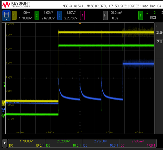
Please see the waveform below, VCC is not stable about 400ms then it is stabled.

Could you advise me to improve this symptom?

I also attach the schematic, Please review it.
Best regards,

Chase

  • Hi Chase, please see below my schematic review and takeaways:

    Schematic:

    -Please update C1 to a 0402 15nF 50V X7R cap. This cap is essential for optimal performance as it provides low impedance at the fundamental fsw. This cap will improve start up, inrush current, regulation and low EMI.

    -Connect 0402 15nF cap next to (VINP-GNDP) pins. Place it as close as possible to the pins for best performance.

    -Add a 0402 15nF 50V X7R cap at the output side next to (VCC-GNDS) pins. Same idea than above.

    -Ferrite bead: for low EMI (if this is a priority) we recommend adding a 2.2uH DM inductor with good current rate (suggestion: 74479763222 or 74479275222 depending on power demands).

    -22uF 16V at the input and output side look good. For low footprint, I recommend a 22uF, 0805, 10V PN: GRM21BZ71A226ME15L. DC bias is lower (10V) but it decreases you footprint.

    -This updated (specially the 0402 15nF cap) should resolve your issue.

    Thank you

  • Dear Manuel,

    Thank you for your support.

    My customer tested again as you suggested, but similar output is still observed.

    They think that one kind of fault situation might be happened when the power is up, because same waveform as output is observed on FLT pin.

    One more thing, the period of fault is random even they tested same PCB, same IC.

    Do you have any advise to fix this situation?

    Best regards,

    Chase

  • Chase, please see below my feedback.

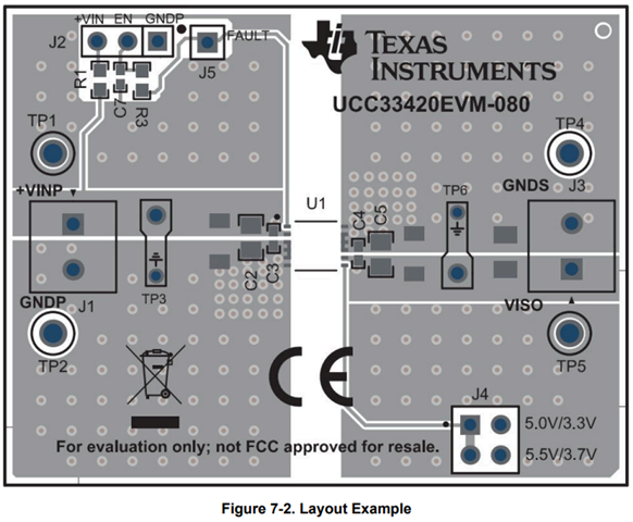
    -Firstly, please share your layout with the updated changes recommended above to be reviewed. Please confirm that 0402 15nF caps were used and connected next to input and output pins. Below is an example of a good layout from the EVM of UCC33410.

    -Secondly, please take a picture of the markings on the UCC33410 device to confirm the PG version of the device you are using.

    -Thirdly, could you please confirm the Ta that this is happening? Is this at ambient temperature Ta=25C? or at lower Ta temperatures?

    -What are the load conditions of this? Is this at no load?

    -What is the sequence followed for the start-up? Are yellow and green waveforms (VINP-GNDP) and (EN/FLT-GNDP) respectively? Are you probing at the EN/FLT pin or before the 10kohm resistor (left side of R1)?

    -The PG version that you are using have the limitation explained below. For a successful start-up, the device needs to be started up following the sequence explained below. In your case VINP is shorted to enable before the 10kohm resistor. However, this should not happen at Ta=25C. You can try the following:

    a. Follow the sequence, applying +5V directly before or after (directly at EN/FLT pin) the 10kohm resistor and then apply VINP.

    b. I suspect that the FB is limiting the inrush current and that might affect the start-up sequence. Try again removing the FB. You can try with VINP shorted to enable first and then if that does not work try following the sequence explained in a.

    -Finally, we are RTM (releasing to the market) UCC33420 on 12/18 with the final PG revision where this limitation is overcome. If needed, we can send samples to customer. Just send me a private message with your email and I can redirect you to my team.

    Thank you

  • Also, please replace 10kohm resistor with a 18kohm or higher resistor so that you ensure FLT is monitored correctly.

    Thank you

  • Dear Manuel,

    Thank you for your support.

    I will post my customer's feedback right after I get it.

    And you said that we are RTM (releasing to the market) UCC33420 on 12/18 with the final PG revision where this limitation is overcome.

    Is it same for UCC 33410? I will send friendship request for the request.

    Best regards,

    Chase

  • Hi Chase,

    We can OTP program one of the UCC33420 devices in order to change the output voltage to 3.3V/3.7V.

    Thank you