This thread has been locked.

If you have a related question, please click the "Ask a related question" button in the top right corner. The newly created question will be automatically linked to this question.

TPS65320D-Q1: Calculating Max Switching Frequency

Part Number: TPS65320D-Q1

Tool/software:

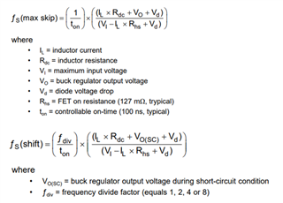
I'm attempting to calculate the max switching frequency for my application using equations 4 and 5 from the datasheet (pg. 14). 
Question:

  1. Given that equation 5 only applies during a short-circuit event, what values for the inductor current and the diode forward voltage should be used? It makes sense to the typical values for my application in equation 4, but not equation 5. Should it be the max current that can flow into VIN and the diode voltage drop at that current?  
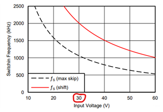
  2. If I use all the example values given in Section 7.3.1.12 of the datasheet my calculated frequencies (fs(max skip) and fs(shift)) do not match Figure 9. Here are the input values I used and my calculated frequencies at Input Voltage = 30V:
IL (A) 1
Rdc (Ohm) 0.13
VI (V) 30
VO (V) 3.3
Vd (V) 0.5
Rhs (Ohm) 0.127
ton (sec) 0.0000001
VO(SC) (V) 0
fdiv  8
fs(max skip) (kHz) 1293.912
fs(shift) (kHz) 1659.369

This doesn't match Figure 9 at Input Voltage = 30V, fs(max skip) ~ 1050kHz and fs(shift) ~ 2000kHz
Am I doing the calculation wrong or is the figure in the datasheet incorrect? 

  • Hi Adam,

    Thanks for reaching out. I am going to help you understand the curve in little more details.

    I checked the calculations are you are correct in those numbers. Please note that the black dashed line represents the typical maximum switching frequency to avoid pulse skipping. Looks like for the graph showing the typical curve, small values of Rdc and Vd are ignored compared to the large output voltage,Vo, of 3.3V, resulting fs(max skip) as ~ 1086kHz.

    Regarding the solid red line, this is maximum switching frequency for the safe operation of the converter under short circuit(V0=~0V) conditions. For the graph looks like, Vo(SC) of ~0.1V is used to calculate the maximum frequency as ~2000kHz.

    Hope that clarifies your questions.

    Sathish

  • You're saying that they modified Equation 4 for fs(max skip) and removed Rdc and Vd? It doesn't make sense that the figure wouldn't use the equation as given in the same section of the datasheet. 

    Right above the figure the text says, "In Figure 9 the solid line illustrates a typical safe operating area regarding frequency shift and assumes the output voltage is 0 V". It says they are using 0V, not 0.1V. 

    If you are correct, there is at least one error in the datasheet.

    Any guidance on my question #1? In my application the typical current draw is 0.1A but the supply connected to VIN is capable of 5A. Should I use 5A when calculating fs(shift)? 

  • Hi Adam,

    You are correct that the graph is not exact representation of the equation but more of showing the typical trend of the frequency vs. input voltage. You can see the graph as a general example as the plot shows max vin of 60V while the max recommended operating input voltage of 36V. However, the formula is the exact calculation of frequency for a given input voltage.

    Regarding question # 1, i would use the load current right before the output short condition.

    Hope that clarifies your questions.

    Sathish

  • Ok, thank you for the guidance.