This thread has been locked.

If you have a related question, please click the "Ask a related question" button in the top right corner. The newly created question will be automatically linked to this question.

TPS40305: Design is not working as expected

Part Number: TPS40305

Tool/software:

Hi expert,

I designed BUCK circuit using TPS40305 is controller.

Spec: Vin = 12V, Vout = 5V, Iout max = 10A.

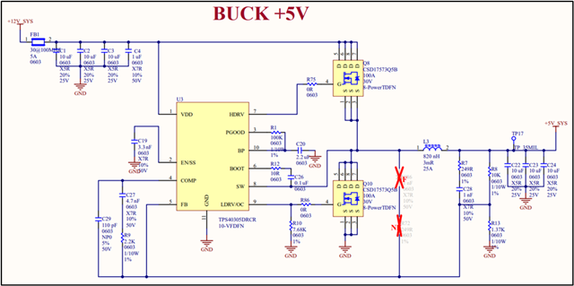
I followed ref but when bringup, I meet some issues. I measured Vout and get 3.7V instead of 5V (no load).

Monitor temperature Tcase of controller is > 90*C. That is strange.

I captured some images waveform from my board: Gate_H_side/L_side Mosfet, COM pin, FB pin as bellow.

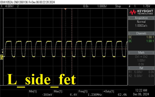
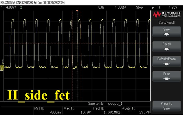
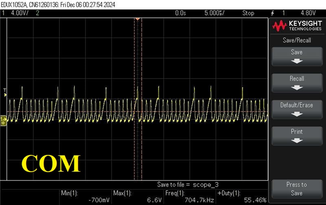
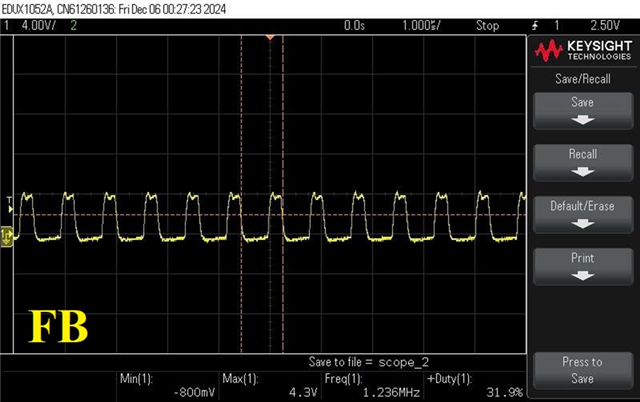
Please check and advise.

Thank you

  • Nien,

    Where did the reference design come from?

    The CSD17573 are very large MOSFETs to be switching at 1.2MHz for a 5V, 10A application.

    The TPS40305 controller uses a 6.5V gate drive and the CSD17573 MOSFETs have about 75nC of gate charge at 6.5V.  With 150nC of gate charge each switching cycle and a 1.2MHz switching frequency, the VIN to BP LDO is trying to support 180mA of gate driver current from a 12V source for about 2W of power dissipation inside the TPS40305 controller.  That is likely causing the controller to overheat and shutdown through over temperature protection.

    Additionally, the large MOSFET and resulting slow rise and fall times of the switching node are likely generating significant switching losses, further heating the components.

    I would recommend trying a MOSFET such as the CSD17507Q5Q, while the Rdson is higher at 11.6mΩ, it has much lower gate charge, only about 4nC @ 6.5V which will provide for much faster switching and lower gate-drive and conduction losses.

    You will also need to adjust the R10 ILIM resistor value for the higher Rdson