A related question is a question created from another question. When the related question is created, it will be automatically linked to the original question.
If you have a related question, please click the "Ask a related question" button in the top right corner. The newly created question will be automatically linked to this question.
Could you please attach the filled out LM51772 Design Calculator to this thread? This would be the most efficient workflow for us to do a schematic review.
the schematic image is very hard to read esp. the pins of the LM51772 are not read able.
To your last comment first:
C3514, R3519, R3520 Remove : OK
nRST to Vin, : required
Please see below my review list and bold marked line items which should be checked again (Note: other info are left here to give an overview of what has been checked)
Checked with Quickstart Calculator
Slope compensation should be set to 1.5 see line 36 -> R_CFG1 = 8.3k
Inductor de-rate could be set to 20% -> R_CFG3 = 2.7k
Cross over frequency is much to high -> recommend is 28k
Phase margin too low : should be > 60 Degree (note: check over full Vin range)
Losses seems quite high - check if this is OK with thermal disipation
Schematic:
Rcs in series with inductor and before inductor
Check filter for Rcs Current sense Resistor Rcs does not have the required filter
Check filter for Risns Current sense Resistor Risns does not have the filter - recommend to add place holder
Connect IMONOUT to VCC if ISNS not used Connect ILIMCOMP to VCC2 if ISNS not used
Snubber on SW1 and SW2 Place Footprint for a snubber at SW1 and SW2 (they can then be populated in case needed (e.g. due to EMI) without layout change) Note: Snubber connect Resistor to GND for better Thermal performance
BIAS connected If BIAS is not used connect to GND or VIN of VOUT (do not keep open) BIAS can be connected to VIN (if the max ratings of BIAS are not violated) to benefit from the better performance of the LDO on BIAS
Add Series Resistor into MOSFET Gate signals lines (they can then be replaced in case needed (e.g. due to EMI) without layout change, additional option: add a diode in parallel for slow on and fast off. Note: Good starting value is 2.2Ω and then adjust in when testing out the PCB
Voltage rating of MOSFET (Have a margin of 30% is recommended)
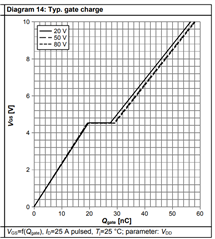
Miller Plateau of MOSFETs used MOSFETs need to be logic level MOSFETs - can be seen by Miller Plateau in the range of 2.5V-3.5V Do not recommend to use this MOSFETs
UVLO setting relative to lowest input voltage UVLO is set to xV but operating range starts at xV - relative large distance
Cap at VCC 22uF : (Datasheet min: 6uF with DC Bias) please check the cap on Vcc to have the required capacitance considering DC BIAS - we use a 22uF on the EVM
VCC2 is for control and driver supply VCC1 can used for external logic - if not used can be disabled
Feedback divider identical for FB and FBIN (check if FBIN is required)
FB_IN required: for pass through mode - only with external FB divider. With internal FB (FB connected to VCC2) put this to AGND
LM51772: Connect FB to VCC2 if voltage should be set via I2C