This thread has been locked.

If you have a related question, please click the "Ask a related question" button in the top right corner. The newly created question will be automatically linked to this question.

TPS61236P: Effective input and output capacitance requirements

Part Number: TPS61236P


Tool/software:

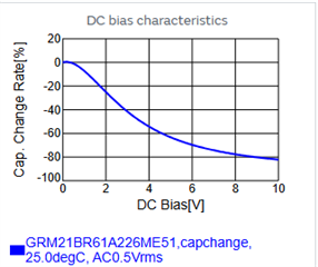
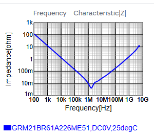
I have been studying the behavior of TPS61236 in detail using the TPS61236EVM. I'm trying to learn something about the margins of stability for the EVM layout and component choices, and I found a few surprising things. First, the datasheet output capacitance spec is 10 uF minimum "effective capacitance". A footnote mentions the negative effects of voltage bias on capacitance, which I was expecting. However, there is not mention of dissipation factor D or frequency effects. I looked closely at the datasheet for the Murata GRM188R60J capacitors in the EVM BOM, and their capacitance is specified at only 120Hz for C>10 uF and 1kHz smaller capacitances. I desoldered and measured capacitance of the 10uF and 22uF caps in the EVM with my PM6304 Analyzer and found that these capacitors are virtually useless above 1 kHz. At 120 Hz, parts are well within spec, but my Analyzer sees them as resistors with a little parallel capacitance at less than 10 kHz. It seems that it's unrealistic to expect much from large value 0805 10V caps at even mid audio frequencies. The EVM schematic uses 3 22uF caps in parallel, with no other capacitors. Is it possible that this converter will be unstable if I install high quality output caps? I will continue my bench investigations. Meanwhile, does anyone from TI have any comment? 

  • I spent a lot of time using the Murata MLCC technical query site: https://ds.murata.co.jp/simsurfing/mlcc.html

    This app provides much more technical data, including detailed frequency response. The data for parts like GRM21BR61A226ME51 look really encouraging, except for this:

    which I was expecting. With 5V bias (as in TPS61236EVM design), you can expect only about 40% of the nominal capacitance, say about 9 uF for a 22 uF cap. Impedance versus frequency response is shown as:


    So, now I need to figure out why my PM6304 thinks it's a resistor above 1 kHz.

  • For those who might be following this obscure posting, I discovered today why my Fluke/Philips PM6304 RCL Analyzer showed high value Murata MLCCs as resistors above a few hundred Hz. In short, I was using the PM9542 remote probe and discovered one of its limitations. When I connect the SMT Adapter directly to the front panel of the PM6304, I get results very much like those seen at  https://ds.murata.co.jp/simsurfing/mlcc.html. Namely, capacitance actually RISES a bit at 100 kHz, to about 25 uF for 22 uF nominal caps. Also, DC bias effects are very much like those shown in the first graph above. So, for the output caps, the effective capacitance of 22 uF caps with 5V bias (as with the EVM) is probably around 9 uF and the SRF is above 1 MHz. The EVM is quite stable with just one 22 uF cap installed. I'm going to experiment a bit further with smaller values.