This thread has been locked.

If you have a related question, please click the "Ask a related question" button in the top right corner. The newly created question will be automatically linked to this question.

LM5021: About disabling pulse skip

Part Number: LM5021
Other Parts Discussed in Thread: TL431, UCC28C42,

Tool/software:

Hi team,

In the datasheet, it says that pulse skip can be disabled by adding >125mV offste to CS pin. And below example are shown.

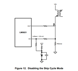
What will be the recommended circuiot for adding the offste? Is it the one in Figure 12, using the zener diode and Vcc? Or should they use other kind of regulator?

Regards
Ohashi

  • Hello,

    Both of those circuits will work for adding the 125 mV offset.

    Regards,

  • Hi Mike,

    Thanks for your comment.

    For pulse skip mode, seems that it will be active when COMP pin voltage is lower than 1.625V. Without adding offset to CS pin, how can the customer make the pulse skip region smaller in the light load condition. One way is to add a dummy resistor at output, but is there any other way to make the COMP pin voltage higher at light load? Can they achieve it by adjusting the opt coupler+TL431 circuit?

    Regards
    Ohashi

  • Hello,

    Your inquiry has been recieved and is under review.

    Regards,

  • Hello,

    You are correct that if COMP is above 1.625 V the design will not pulse skep.

    At light loads if the design does not need duty cycle the comp voltage will decrease.  You can avoid it with what you had suggested as a dummy load to keep it out of this region.

    You could increase the size of the current sense resistor so at lighter load the CS signal is higher and comp signal is higher at lighter loads.

    Regards,

  • Hi Mike,

    Thanks for your comment.

    How about adding a dumy resistor at COMP pin to give 125mV offset to COMP pin? Adding 120Ω parallel to photo coupler transistor to add 125mV offset to COMP pin.

    You could increase the size of the current sense resistor so at lighter load the CS signal is higher and comp signal is higher at lighter loads.

    The cons of making Rcs large is that the maximum output power will be smaller, right?

    Regards
    Ohashi

  • Hello,

    Your inquiry has been recieved and is under review.

    Regards,

  • Hi Mike,

    In addition to above question, could you tell us the disadvantage of adding 125mV offset to CS pin to diable the pulse skip?

    Regards
    Ohashi

  • Hello,

    You are correct that if you use a larger current sense resistor, the maximum output power will be reduced.

    Adding the 125 mV offset to the current sense signal is the recommended way to disable cycleing skipping.  By adding this you will go into power limiting 125 mV earlier.  This means the maximum current limit will be 500 mV - 125 mV = 375 mV.

    I do have another idea for you.  The LM5021 is a general purpuse PWM similar to the UCC28C42 family of devices.  These devices do not have the cycling feature and do not have to disable it.  I would recommend that you use one of these devices instead.  Then you will not have to disable the cycle by cycle current limiting.

    https://www.ti.com/lit/ds/symlink/ucc28c42.pd

    If you have questions about using the UCC28C42 please repost in the e2e with UCC28C42 in the title.

    Thank you for interest in Texas Instruments (TI) products.  If you have a related question, please click the "Ask a related question" button in the top right corner. The newly created question will be automatically linked to this question.

    Regards,