LM74500-Q1: LM74500-Q1 Reverse Polarity. Need to tolerate 110V positive

Part Number: LM74500-Q1

Tool/software:

You didn't really answer the question I asked regarding adding a resister in the gnd lead to float the device.  I've taken care of downstream devices another way since I can't disconnect during a surge and must operated through it.  This chip is only for reverse voltage.  I'm having problems with this LM74500-Q1 controller at lower voltages (20V) and I believe it is because I have a 51K resistor from the chip gnd to gnd to float this.  I need to speak to someone familiar this chip.  In the datasheet there is a figure 7-2 which shows a huge spike in quiescent current at ~ 2 - 5V Vsource voltage.  I think this 650uA spike may be causing a start up problem since I have a large resistor in the ground lead to float the chip.  I need to understand if figure 7-2 is with the enable high or not?  If I delay my enable instead of tying to Vsource can I reduce huge 650uA current spike at startup?  Is there someone I could work with quickly on this?

Regards,

Jeremy

  • Hi Jeremy,

    Welcome to E2E,

    Do you want the device to tolerate 110V DC or transients?

    High spike in Iq is when the charge pump is charging.

    Regards,

    Shiven Dhir

  • Shiven,

    I need to tolerate 110V transients.  So regarding the spike in Iq.  If I start with the charge pump disabled and Vsource is > 5V when I enable will I see the same current spike shown in figure 7-2 or not since Vsource is above 5V?  Is figure 7-2 assuming you are starting from Vsource = 0V and ramping up to 65V with the charge pump enabled?

  • Hi Jeremy,

    When Vsource <5V, the charge pump works in always condition and the Iq remains high throughout. When Vsource >5V, the charge pump works in ON/OFF scheme and average Iq is reduced.

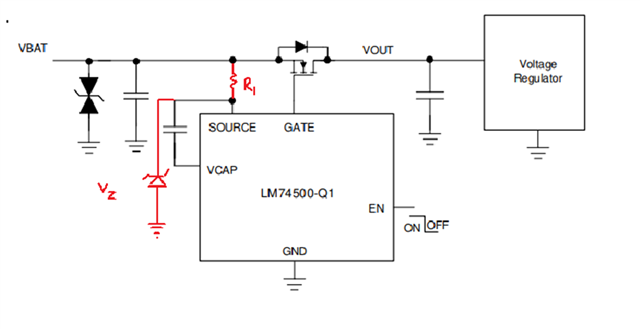
    You can use LM74500-Q1 as shown to sustain 110V transients.

    Regards,

    Shiven Dhir

  • Shiven,

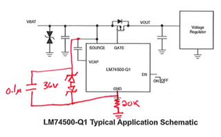
    I'm not sure it is a good idea to configure it the way you have shown.  This puts a large resistor in series with the gate source drive to the FET.   I believe the resistor should go in the ground lead.  See my schematic below.  Thanks for clarifying the charge pump behavior.  Based on this there is no way to avoid this current spike at startup.  I decreased my ground resistor to 20K which floats the IC and it it working fine now.  I just had too large of a resistor because I missed this key detail of figure 7-2 when I originally selected a 50K resistors.

  • Shiven,

    I'm seeing a problem with this controller.  If the slope of the rising voltage is too fast it appears to never start running.  I shorted the ground resistor and just ran at  my normal 28V and still see the problem.  Are there any known startup issues with this controller related to the slope of the rising input voltage?  These aren't very fast rise  times even like 20ms seems to prevent the controller from running.  If the input voltage rise is slower like 100ms then it turns on and runs.

    Regards,

    Jeremy

  • Hi Jeremy,

    Yes, adding resistor as I showed will add impedance in gate-source. If that is not acceptable, adding a resistor in ground path should be fine as well.

    Can you share the waveforms of the failed startup behavior? I do not expect this to happen.

    Please probe VIN,VOUT,GATE,VCAP

    Regards,

    Shiven Dhir

  • Shiven

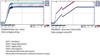
    I've attached a slide showing a fast rise (4ms) and a slow rise (2 seconds).  I can see the gate voltage is continually pulsing on the fast rise. It is unclear why this is discharging - it seems the IC must be discharging this gate. On a very slow rise it charges the gate of the FET with out discharging.  Note: once I added the scope probes I had to slow down the rise more to see the good case.  I have some pretty high gate capacitance FETs, approx 10nF x 4 of them = 40nF.  I'm wondering if I need a bigger cap for the charge pump than the recommended 0.1uF.   Note: I changed the Vin slope by changing the current limit of my input power supply.   Note sure how this resolution will show up on this image in this system.  Let me know if there is a way to work directly via email if you need a higher resolution image.

    Regards,

    Jeremy

  • Shiven,

    I know this charge pump cap should be ~ 10x the gate cap.  I saw the recommended value of 0.1uF and didn't notice it was a min value and designed it in.  I finally found where in the datasheet that 10X is recommended as well.  I bumped up the charge cap to 1uF and seems to be fine now.  I'll let you know if I run in to any other issues.

  • Hi Jeremy,

    Glad you found the root cause. You can reply to this thread in case of any further issues. Closing for now.

    Regards,

    Shiven Dhir