Other Parts Discussed in Thread: TPS55287
Tool/software:
Hi Ti team
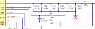
I have designed the circuit based on Webench.
I would like to request your review.
please note that the components I used are in millimeter units.
I have a few questions:
-
Is it necessary to separate AGND? Does AGND apply only to analog components?
- I am using audio, but the distance is over 50mm.
-
Are the BOM components of the EVB in inch units?
-
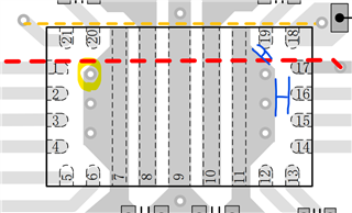
Can I use 0.5mm vias under TPS?
-
For the blue line shown in the picture, how much spacing is recommended?
Thank you for your assistance.
Regards.
Jeong.