This thread has been locked.

If you have a related question, please click the "Ask a related question" button in the top right corner. The newly created question will be automatically linked to this question.

UCC256404: Surge immunity Issue fro UCC256404 and UCC28019

Part Number: UCC256404
Other Parts Discussed in Thread: UCC28019, UCC24624

Tool/software:

Dear Sir,

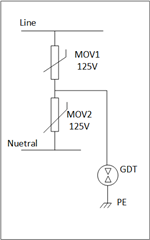
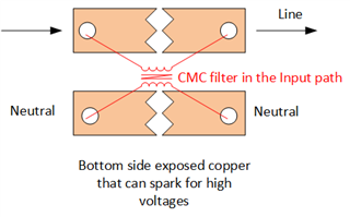
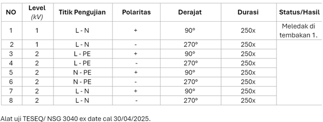
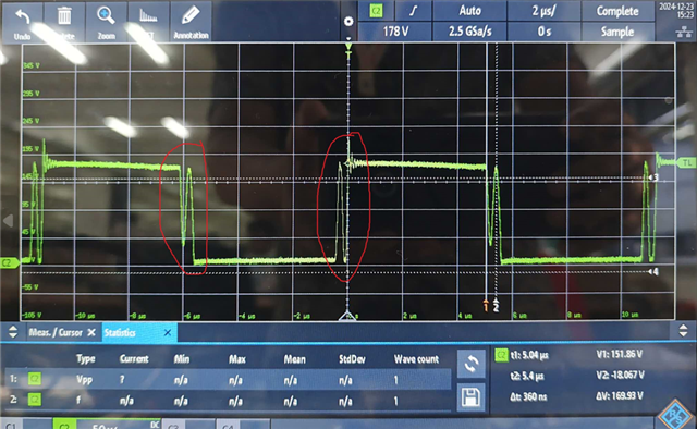
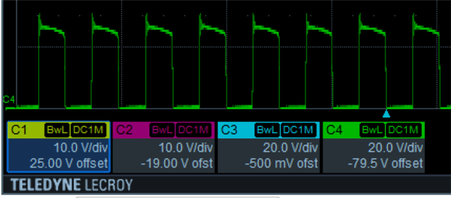
I have new issue with surge immunity for my charger for EV new design

the issue is when surge immunity test the POWER MOSFET for half bridge,POWER MOSFET  soft start and PFC controller UCC28019  always damage  ,please help me how to solve (throuble shoot) that issue.

There's the attached for schematic diagram and pcb design .

Thanks and Best Regards ,

Supardi

850W CHARGER EV 2024-12-11.pdf850W CHARGER EV 2024-12-11.zip 

  • Hi Supardi,

    Your query is under review. I will respond by 12/12.


    Regards
    Hemanth

  • Dear Hemant ,

    Thanks for your support ,wait your review and get solution for my issue .

    Regards

    Supardi

  • Hi Supardi,

    Meeting surge requirements is a system level requirement, not necessarily something to do with the controller.

    Nevertheless, what type of surge do you apply? Do you have voltage rating, series impedance values? Is it common mode or differential mode surge? Based on that, you might need to take different remedies.

    To debug:

    Measure the Bulk voltage, VDS of the FETs that damage during surge (using HV differential or isolation probes) and observe them on oscilloscope to understand whether they fail due to D-S voltage breakdown or some other reason. Based on that you could try different solutions.

    • You could try adding GDT.
    • More capable MOV between line and neutral.
    • Try double MOV between Line and Neutral with half voltage rating each and connect the middle node to PE as shown below.

    • Add spark gap under CMC in bottom layer of PCB with exposed copper (without solder mask) in line and neutral path, so that the CMC inductance is bypassed (at least to some extent) during surge.


    • Add a 2nd stage common mode choke with spark gap. (If possible, add it in the footprints of L502, L503 temporarily for debug purpose). 
    • Ensure you maintain proper clearances (L, N, PE to LV) where the high surge voltages propagate, so that the LV circuits are not affected.

    All the best!

    Regards
    Hemanth

  • Nevertheless, what type of surge do you apply? Do you have voltage rating, series impedance values? Is it common mode or differential mode surge? Based on that, you might need to take different remedies.

    Dear Hemanth

    We use test method like as this 


    The Power Mosfet damage at the first shot.

    Thanks and Regards

    Supardi

  • Hi Supardi,


    Thanks for the details.

    Please follow the above steps to debug and improve the performance.

    Even for a series differential inductor, add spark gap (or LV GDT) across it, if the voltage across inductor measured to be high. So, that the voltage across the inductor is clamped / limited to a certain value.

    Regards
    Hemanth

  • Hi Hemanth ,

    I check the VDS of secondary Mosfet signal at full like as picture ,can you help to explaine how to like that .

    Thanks and best regards,

    Supardi

  • Hi Supardi,

    Do you mean this VDS waveform is of T512 / T520 FET during surge event?

    If you are asking a different question than the subject, I request you to submit a new question with appropriate subject and tags.

    Regards
    Hemanth

  • Dear Hemanth ,

    I check the VDS of T512/T511 at normal condition full load before surge test .I compare with EVM like this :

    Thanks and Regards

    Supardi

  • Supardi,

    The EVM has diode rectifiers. The board you are testing seems using a synchronous rectifier with a controller. Please review the SR controller operation, by observing the primary gate drive signals, VDS of SR FETs and VGS of SR FETs.

    Regards
    Hemanth

  • Dear Hemanth ,

    I used the SR controller like as recomendation below :

    this schematic diagram for VDS signal above 

    Thanks and Regards

    Supardi

  • Hello Supardi,

    The design of the UCC24624 needs to be carefully considered to ensure you have the proper components for your design. For example, page 22 of the UCC24624 datasheet shows the formula for the SR MOSFET selection.

    The SR MOSFET that you chose is the IPP220N25NFD. According to the datasheet, the RDS,on is 22mΩ. Plugging this into the formula, your Iout,max is only ~1.43A. While you did not specify your system parameters, at 850W I assume you have a much higher Iout,max and thus you will have very high conduction losses. 

    We have the UCC24624 datasheet and numerous app notes to aid in your design and choose the right components:

    Based on the waveforms, it does not look like you have the turn-off or turn-on time optimized for your design. Regardless, this issue is not related to the original issue of surge immunity. Please follow the suggestions that Hemanth made regarding surge immunity. Surge immunity is not related to the TI controller itself so you may find better resources regarding surge immunity somewhere else.

    Please submit a new question for help with the UCC24624. Please expect a delay in our responses due to the holidays until January.

    Regards,

    Jonathan Wong