Other Parts Discussed in Thread: LM25011
Tool/software:
Hello
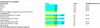
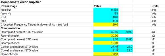
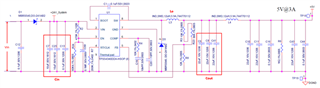
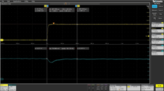
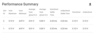
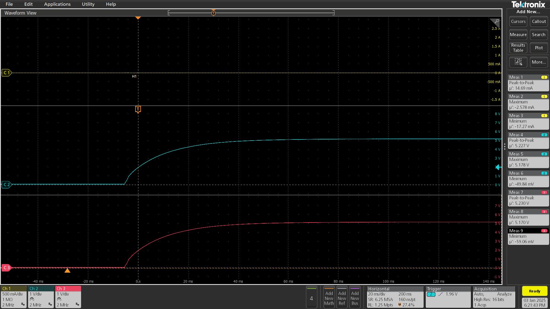
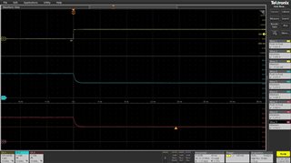
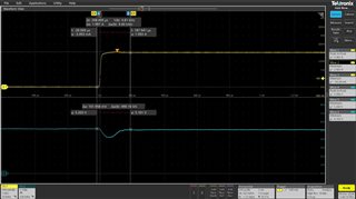
We are facing issue at the transient load response of TPS54340. From transition of output load current from 0A to 2A. The output of TPS54340 dropping from 5V to 4.2V.
Can you suggest any solution. This is the continue design we are using from a while.
As our design parameters as below,
|
Parameters |
Values |
|
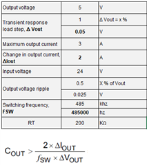
Input voltage, Vtyp. |
24 V |
|
Input voltage, Vinmax |
28.8 V |
|
Input voltage, Vinmin |
11 V |
|
Output voltage of TPS54340 |
5 V |
|
Maximum output current, Iout |
3 AM |
|
Change in output current, Δiout |
0 to 2 A |
|
Pin : RT/CLK of TPS54340 |
200 Kohm |
|
Pin : FB of TPS54340 |
R1 = 66 Kohm and 12 Kohm |
|
Inductor |
12uH,5.9A |
|
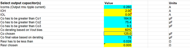
Cout |
22uF || 22uF || 22uF |
|
Total Cout : 66 uF |
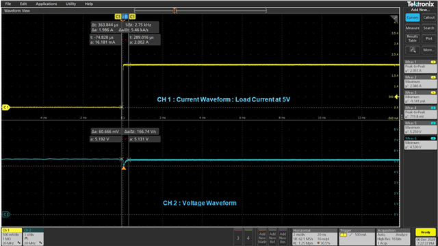
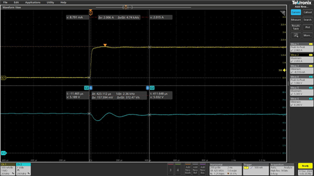
-- Condition : Vin 24V, Vout : 5V, transient load current : 0A to 2A.
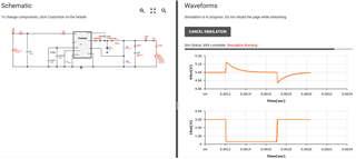
observed waveform as below
Regards,
Virendra