Because of the holidays, TI E2E™ design support forum responses will be delayed from Dec. 25 through Jan. 2. Thank you for your patience.

BQ25628E: Noise at light load

Part Number: BQ25628E

Tool/software:

Hi,

I am creating a custom design using the part. The charging, ADC, etc. functionality works well. However, at light loads (= battery fully charged or no battery) when the system draws about 50 mA from VSYS, VSYS becomes noisy, unstable and the output capacitors audibly buzz. It seems this might have something to do with the PFM mode being activated, but I explicitly disabled PFM (PFM_FWD_DIS = 1).

The status registers are as follows: Charger_Status_0: 00, Charger_Status_1: 0x14, Charger_Flag_0: 0x10, FAULT_Flag_0: 00

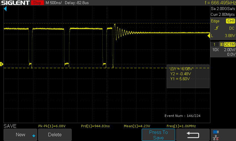
Charger Flag 0 reports (0x10) occasional "Entered or existed VSYS min regulation". I've attached the oscilloscope trace for VSYS below.

The ADC reports the following values, which all look reasonable: Ibus: 74 mA, Ibat: 0 mA, Vbus: 5.136 V, Vpmid: 5.136 V, Vbat: 4.208 V, Vsys: 4.230 V, Tbat 26 C, Tdie: 25 C

How can I ensure a quiet VSYS under no battery or fully charged conditions, please?

Thanks

Martin

VSYS
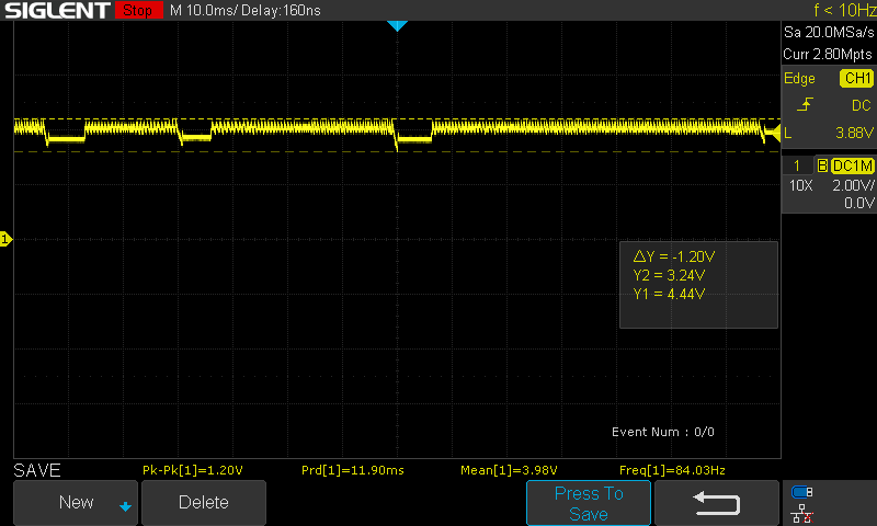
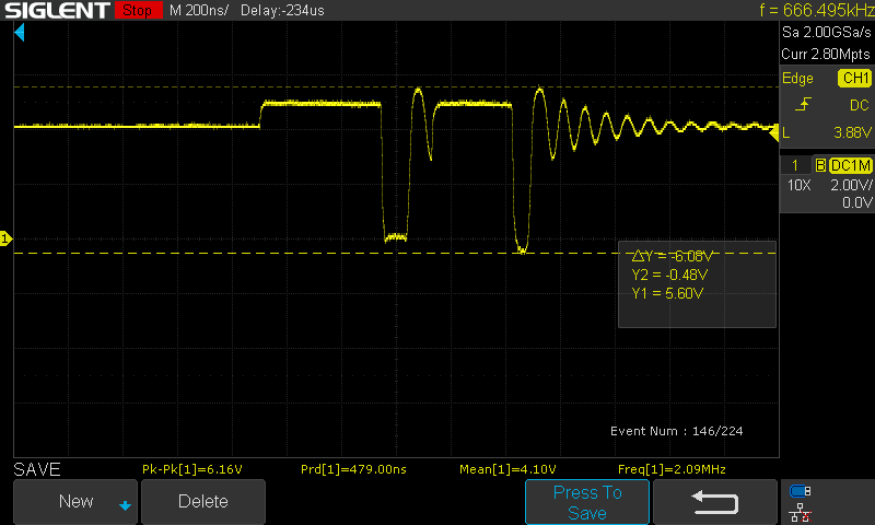
SW node: (first image overall, subsequent images zoomed parts of this trace)
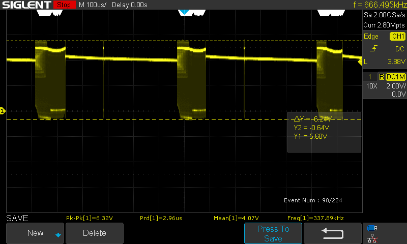
Start of the pulse group
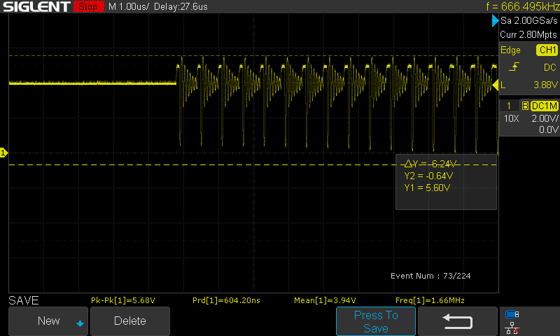
End of the pulse group
Single pulse that appears on SW
  • Hi Martin, 

    Thank you for reaching out via E2E and providing detailed explanation and waveforms of your observations. Please see my comments below. 

    In general on the BQ25628E when operating at no load or very light load you can observe what appears like PFM switching even when PFM_FWD_DIS = 1. The converter is operating in DCM  mode due to such a light load. The duty cycle can become too low and pulses may be skipped appearing like PFM mode switching. 

    In terms of VSYS stability issue, one comment you made which stood out was "Charger Flag 0 reports (0x10) occasional "Entered or existed VSYS min regulation" ". With a fully charged battery connected to BQ25628E device I would not expect VSYS min regulation status to change. Given this I am making the assumption this observation occurred with no battery attached.

    When operating with no battery connected charge must be disabled to ensure stable VSYS regulation. Can you help to check if you still observe noisy/unstable VSYS in no battery case with charge disabled? 

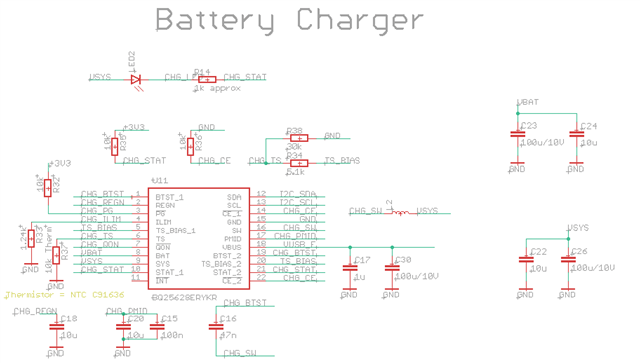
    Additionally, can you share the BQ25628E portion of your schematic so I can review?

    Best Regards,

    Garrett 

  • Hi Garett,

    Thanks for your response. I've tried disabling charging (no battery) and VSYS became much quieter and the buzzing has gone away. The waveform now resembles the oscilloscope trace marked "start of the pulse group" above (PWM with DCM?). I guess I should ensure the charging is disabled whenever the battery is removed but I hoped the charger would figure that out by itself.

    I am also unable to repeat any buzzing noise etc. with the battery full or in top-off but I was convinced I heard it in a fully assembled device with a battery. So perhaps it's only a problem when there is no battery.

    The datasheet notes that the optimal inductor size is 0.68-2.2 µF. Which value should I choose if my peak charge current is 1.5 A (+0.5 A system consumption), and I would like to avoid the DCM mode / ensure VSYS is as quiet as possible? I am currently using the IHLL1210ABEZ1R0M1Z 1 µH inductor.

    Thanks for your help

    Martin

  • Hi Martin, 

    Great to hear the buzzing goes away when charge is disabled with no battery connected. 

    I guess I should ensure the charging is disabled whenever the battery is removed but I hoped the charger would figure that out by itself.

    Unfortunately, the IC does not have built in battery detection. If charge is enabled with no battery connected the device will charge the BAT pin output cap as if it is a very small battery. Your systems MCU host will need to disable charge whenever a battery is removed. We have a high level example of how you can use BQ25628E registers to check for a battery. If you are interested I can help to provide. 

    The datasheet notes that the optimal inductor size is 0.68-2.2 µF. Which value should I choose if my peak charge current is 1.5 A (+0.5 A system consumption), and I would like to avoid the DCM mode

    Using a larger inductor (i.e. 2.2 uH) will help to push the operating point away from DCM operation, but as you mention if issue is resolved by disabling charge you may not need to change from the 1 uH you are currently using. 

    Best Regards,

    Garrett