This thread has been locked.

If you have a related question, please click the "Ask a related question" button in the top right corner. The newly created question will be automatically linked to this question.

LM5156: Flyback design fails under any load

Part Number: LM5156

Tool/software:

He everybody, we have a variable flyback design that fails under virtually any load current.  Specifically the secondary side diode D1801 and the main FET switch Q1800. 
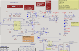
Schematic attached.

This is a 48V to a 135V-205V design, U1803 is an I2C controlled variable resistor that moves the reference voltage up and down accordingly.  The load on the output side can be zero at many times, so operation at that point is important.  I have looked at the current in R1805 and I am seeing huge positive and negative current spikes there which obviously is not correct.  Any smoking guns here?  What should I be looking at to get this operational?

  • I will say that its attempting to regular and at no-load I am getting proper average voltage out of the design.  However during those cases the thing is heating up incredibly, in particular the input caps, transformer, and current sense resistor and there is a low frequency saw tooth on the output with 1Vpk-pk which also isn't right.

  • Hi Michael,

    Thanks for using E2E.

    Has this design been checked with the quickstart calculator? https://www.ti.com/tool/download/SNVC240 Please fill out this file and attach it to the thread.

    What is the maximum load the design is made for?

    First, i would recommend to remove the U1803 and get the design to work without it.

    Can you please provide some scopeshots of the behavior you see?

    I would like so tee Vin, Vout, switchnode and CS pin. In another scopeshot please replace CS with COMP.

    Best regards

    Moritz