Tool/software:
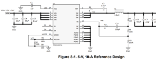
What is the purpose of R1 and R3 here. I am using the same design for my application which also require the same specs i.e. 24 V down to 5V max 8.5A load current . The load is 5V LED strips.

This thread has been locked.
If you have a related question, please click the "Ask a related question" button in the top right corner. The newly created question will be automatically linked to this question.
Tool/software:
What is the purpose of R1 and R3 here. I am using the same design for my application which also require the same specs i.e. 24 V down to 5V max 8.5A load current . The load is 5V LED strips.

R1 is a boot-strap resistor. It limits the current into the BOOT pin that powers the high-side driver during pull-up. This reduces the rising slew-rate on the switching node to limit ringing and reduce voltage stress on the MOSFETs as well as high-frequency EMI noise.
R3 is a resistor in series with the C11 feed-forward capacitor that can be used to limit the high-frequency boost of the feedforward capacitor. Since the Vout / Vref ratio is pretty high, it can be useful to limit the gain boost with a series resistor depending on the needs of the application.
how do I select the values for these two? and what if I don't use them at all as my application is 5V Led strips.
Hi,
Sorry for the late reply because of weekend. Generally speaking, we choose R1 as 0ohm at first. It will be adjusted later based on the actual measured SW waveform, and the maximum value is generally not more than 10ohm. R3 is usually selected as 0ohm first. Then adjust it according to the circuit stability. Thanks.
Aurora