Because of the holidays, TI E2E™ design support forum responses will be delayed from Dec. 25 through Jan. 2. Thank you for your patience.

LM5164-Q1: Layout question

Part Number: LM5164-Q1
Other Parts Discussed in Thread: LM5164

Tool/software:

Hello,

I am using the LM5164 buck IC. 

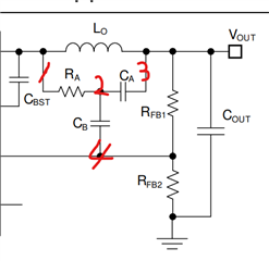
I saw in the datasheet in page 25 that the resistor and the capacitor of the triple 3 circuit is near the inductor and not near the IC. Only the second capacitor of the triple 3 circuit is near the IC.

Why is that?

Thank you

Maor M.

  • Hello Maor 

    Node '1' is switching node which is connected to the SW pin. It is recommended to make this node area as small as possible (or as short as possible) to minimize EMI. 

    RA and CA forms a RC filter. They usually are located close to each other. 

    Then, naturally node'2' and node'3' traces become short.

    Node'4' is connected to the FB pin which is high impedance. In order to minimize a noise injected to this high impedance pin, it is recommended to locate CB, RFB1, RFB2 close to the FB pin. 

    -EL