This thread has been locked.

If you have a related question, please click the "Ask a related question" button in the top right corner. The newly created question will be automatically linked to this question.

TPS65219: about PMIC some problems

Part Number: TPS65219
Other Parts Discussed in Thread: AM623, USB2ANY

Tool/software:

Hi Team,

we have some question would like to understand,

1. as shown in the attachedment slvafd0b, table 3-1 on page 5 shows that TPS65219 has series TPS6521901~TPS6521908 with different voltage, this means that the buck and LDO voltage of this PMIC have different output voltage according to different models, and can't it be adjusted through external H/W?

2. as shown in the attachedment slvucm5, this document mentions that the power sequence and output voltage can be adjusted through the GUI, so what is describe in the above question is only the factory default voltage of the IC?

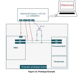
3. in addition, what circuit need to be use this GUI? because there is no relevant circuit in AM623 EVM , only the picture below can be seen in slvucm5, does this require a special fixture to program? or is it USB? is it ok to use I2C dongle?  since we could't  find similar fixture on the TI website, could you provide releant information for us reference?

4. also, if the power sequence and output volatge have been adjusted, does every board produced in the future need to be programmed with the modified configuration through the finture?

5. there any other differences between TPS652190xRHB and RSM reel/tape ?

slvafd0b-Powering the AM62x with the TPS65219 PMIC.pdf

slvucm5-TPS65219 NVM Programming Guide.pdf

  • Hi Tommy,

    Thanks for reaching out on E2E. I am happy to provide answers to your questions.

    1. That is correct. TPS65219xx comes in different variants for supporting different applications. The table shows the default voltages of the factory programmed devices. After PMIC is powered up, the individual rail voltages can be changes by communicating to the PMIC using I2C. Please refer to the individual TRM (Technical Reference Manual) for additional details on Buck and LDO voltage settings.

    2. Correct. For the available device variants, default factory programmed regulator voltages are shown but they can be re-programmed as needed using NVM programming.

    3. In order to change the rail voltages or to re-program the default voltages on the prototype board, you will need access to SDA, SCL, GND and 3.3V supply. You can use any I2C communication box (ex: USB2ANY, available on ti.com) to communicate with PMIC.

    4. For high volume (250Mu+), TI can create a new custom device variant that comes with factory programmed rails or for low volumes customers needs to program the PMIC in production line or work with 3rd party vendors for small fee for programming the PMIC.

    5. Those are different package sizes TPS65219xx is available. RHB comes in 5mmX5mm package and RSM comes in 4mmX4mm package.

    Sathish