- Ask a related questionWhat is a related question?A related question is a question created from another question. When the related question is created, it will be automatically linked to the original question.
Tool/software:
Hello Team,
on customer behalf I would like to clarify discrepancy between TINA simulation and DS specs.
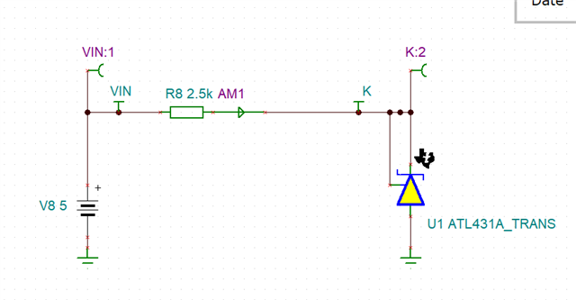
The schematic customer is simulating:
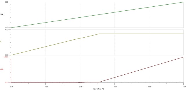
results from simulations:
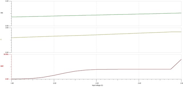
zoomed in
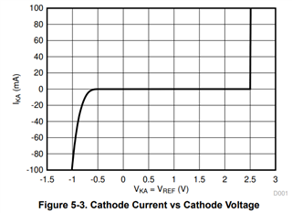
From what is attached in the DS, there is discrepancy between the simulation and what is described in DS:

This is the link to the DS https://www.ti.com/lit/ds/symlink/tl431.pdf
We see that the TL431 is starting to conduct above 1V from the graph above, as from the simulation it starts about 1.8V. Also, it seems the consumed current is also different.
Could you help to understand what the reason for having these differences? Which one is correct and can we rely on the simulation results that we have for our schematic?
thanks,
regards,
Juri