This thread has been locked.

If you have a related question, please click the "Ask a related question" button in the top right corner. The newly created question will be automatically linked to this question.

BQ77905: False CHG FET Signal of BQ7790518

Part Number: BQ77905
Other Parts Discussed in Thread: BQ76942

Tool/software:

Hi,

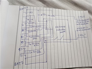
I am using BQ7790518 for Over charge cut-off protection for 8S pack. The schematic is attached below. There are two kinds of charger that we currently have. In one of the charger the device is working fine. For the other charger, the protection board initiates a false gate pull down signal of the CHG-FET during charging so, the battery pack is not able to charge fully. Below I have attached the wiring diagram of the board. I have checked that in the event of CHGFET off, the protection board is not experiencing any OV fault for any of the CELLs. Can you please suggest what can be the reason for CHGFET OFF in this regard?

Wiring diagram

  • Hello Goutam,

    What are the cell voltages during charging? Could it be possible that there is a higher IR drop across thee cells or the cell connectors during charging? 

    I have seen cases where an IR drop during charging causes the voltage seen by the IC to appear larger than what the cell voltage is, leading to early termination.

    If you lower the voltage to below the hysteresis, does the part recover from the fault?

    Best Regards,

    Luis Hernandez Salomon

  • Hi Luis,

    The CELL voltages are 4.079V, 4.120V, 3.998V at the entrance of the board and are less than 4.15V and the IC recovers from fault immediately after the charging stops and that I am assuming that is in line with the IC recovery time of 180ms. Is this due to the net tie connected between the IC GND and the BATT- terminal?  The high current flowing through the ground may cause voltage fluctuations? Shall I use some filtering at the ground such as inductive choke or may be a cap between the two grounds?

  • Hello Goutam,

    I think that could be possible, if the voltage difference between IC GND and BATT- is large enough, but I think it would be unlikely. 

    My guess is that OV is triggering, due to a cell probably measuring above the OV threshold during a charging current. Then when charging stops, the cell relaxes or the IR drop stops, causing it to recover.

    Best Regards,

    Luis Hernandez Salomon

  • Hi Luis,

    Can you please recommend any changes in the schematic and grounding ASAP? We need to release this at the earliest.

  • Hello Goutam,

    There is nothing in particular that I think may require change. I think one thing you could do would be to measure with a scope the signals to narrow down what could be causing the protection to trigger. For example CTRC/CTRD could be measured to check if it is the top IC or bottom IC that is causing the fault. 

    Once that is done, you could check individual VCx of that IC to see if there is an input that measures above the OVP of the device.

    Best Regards,

    Luis Hernandez Salomon

  • Hi Luis,

    Thank you for your suggestion. As per our schematic for 8S configuration, the top device CTRC and CTRD is connected to the local gnd, i.e. CELL3, so I should read around less than 12.6V. For bottom device, can you suggest the nominal as well as maximum readings of CTRC and CTRD? Is it VDD+5V = 17V max?

  • Hello Goutam,

    The engineer is currently Out of Office for today and tomorrow. They will be back Monday to provide a response.

    Thank you for your patience.

    Best Regards,
    Alexis

  • Hello Goutam,

    The voltage would likely be a few volts above BAT for the FETs to remain ON. 

    What I would recommend is to measure it when you know that both MOSFETs are ON. Then measure again when you see that there are MOSFETs turned-off. If you see the level of either one changed and it corresponds to the MOSFET that turned-off. Then the protection was triggered by the upper die.

    Best Regards,

    Luis Hernandez Salomon

  • Hi Luis,

    Thanks for your suggestion. Can you recommend any TI device similar to BQ7790518, does OV cutt-off at 4.50V and supports upto 8S configuration?

  • Hi,

    The engineer will be out for winter holidays until the New Year.

    Thank you for your patience.

  • Hello Goutam,

    The most similar device would be the BQ76942, which is a 3s to 10s monitor/protector. This device can be OTP programmed with your custom settings and be used standalone. 

    If it is OTP'd, an MCU would not be required, but you would require a special manufacturing flow to OTP program the device.

    Best Regards,

    Luis Hernandez Salomon

  • Hi Luis,

    Thank you for the suggestion. However, we are looking for a very cheap solution with 4.3V to 4.5V OV protection with 7V-12V FET drive for charge cutt-off, without any MCU involvement. Can you please suggest if any?

  • Hello Goutam,

    Like I said, you could use the BQ76942:

    BQ76942, which is a 3s to 10s monitor/protector. This device can be OTP programmed with your custom settings and be used standalone. 

    This can be OTP'd (One Time Programmed) with your settings, then it will not need an MCU to function.

    Best Regards,

    Luis Hernandez Salomon