This thread has been locked.

If you have a related question, please click the "Ask a related question" button in the top right corner. The newly created question will be automatically linked to this question.

TPS40090: pwm signal discountinued

Part Number: TPS40090
Other Parts Discussed in Thread: UCC27223, INA849

Tool/software:

hi

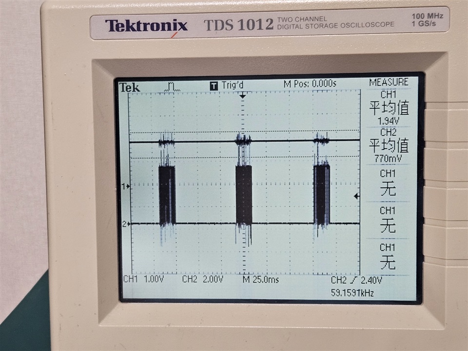
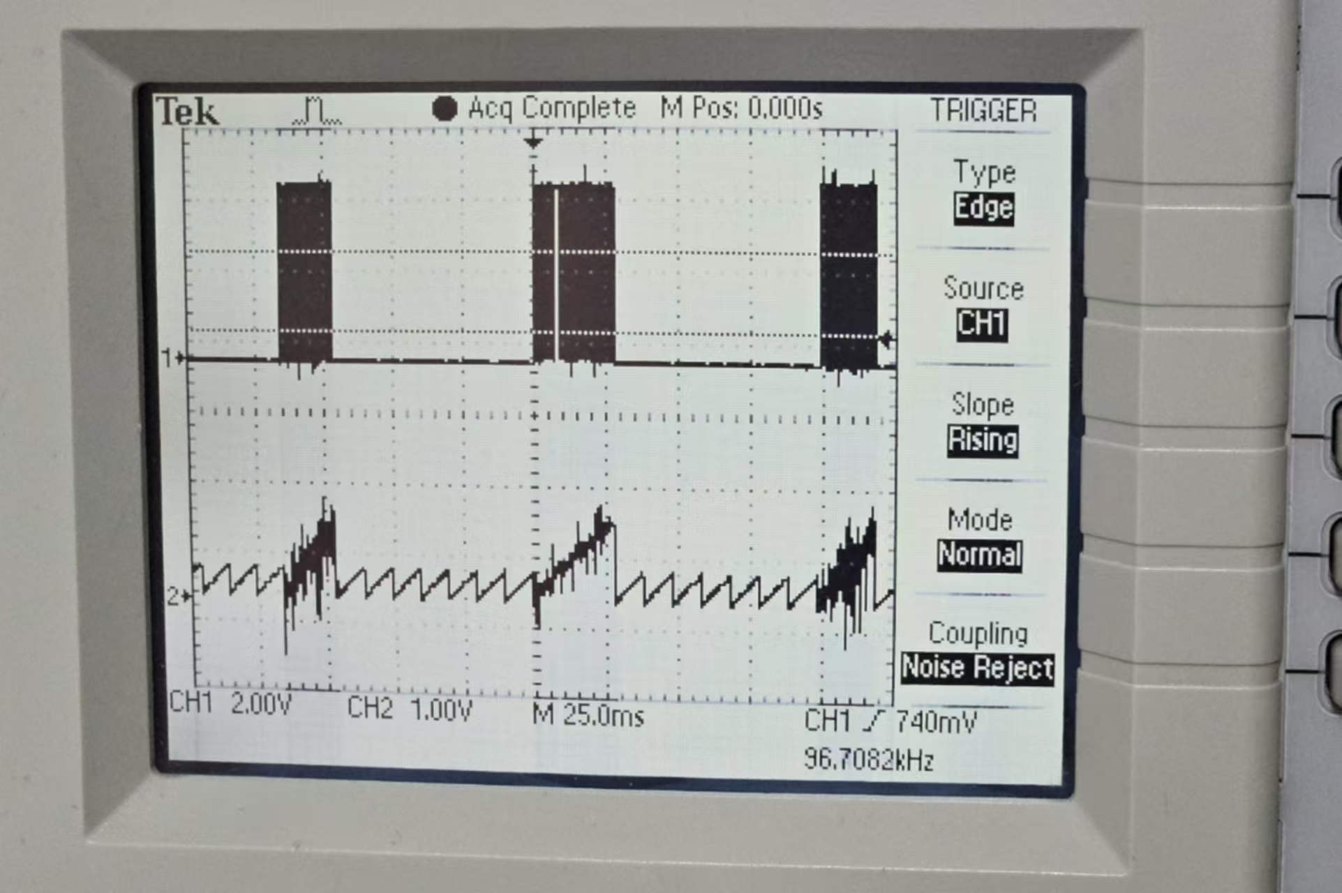
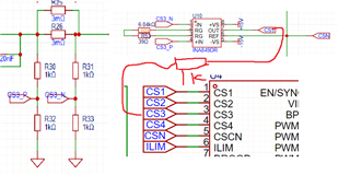
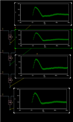
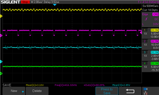
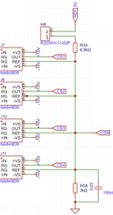
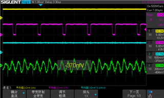
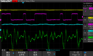
i use tps40090 and ucc27223 make a 4 phase buck controller,because i need constant current control,so i bypass the internal err opamp,use external err opamp and connect the output to tps40090 comp iput directly,and use instrument opamp to acquire each phase inducor current。when powered up ,the pwm signal seems strange,it works as the picture,all 4 phase pwm signal will shutdown few millionsecons and then back to normal。

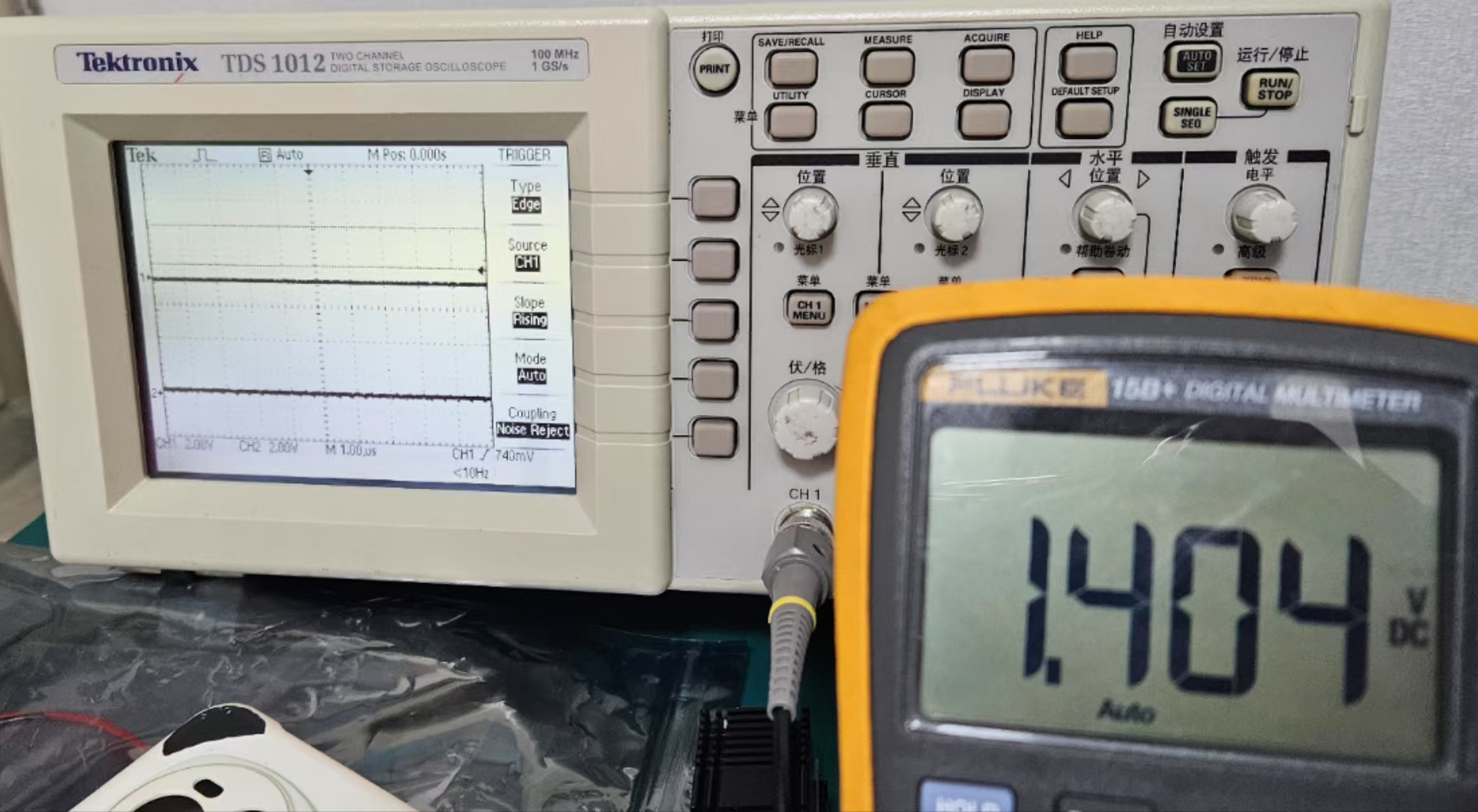
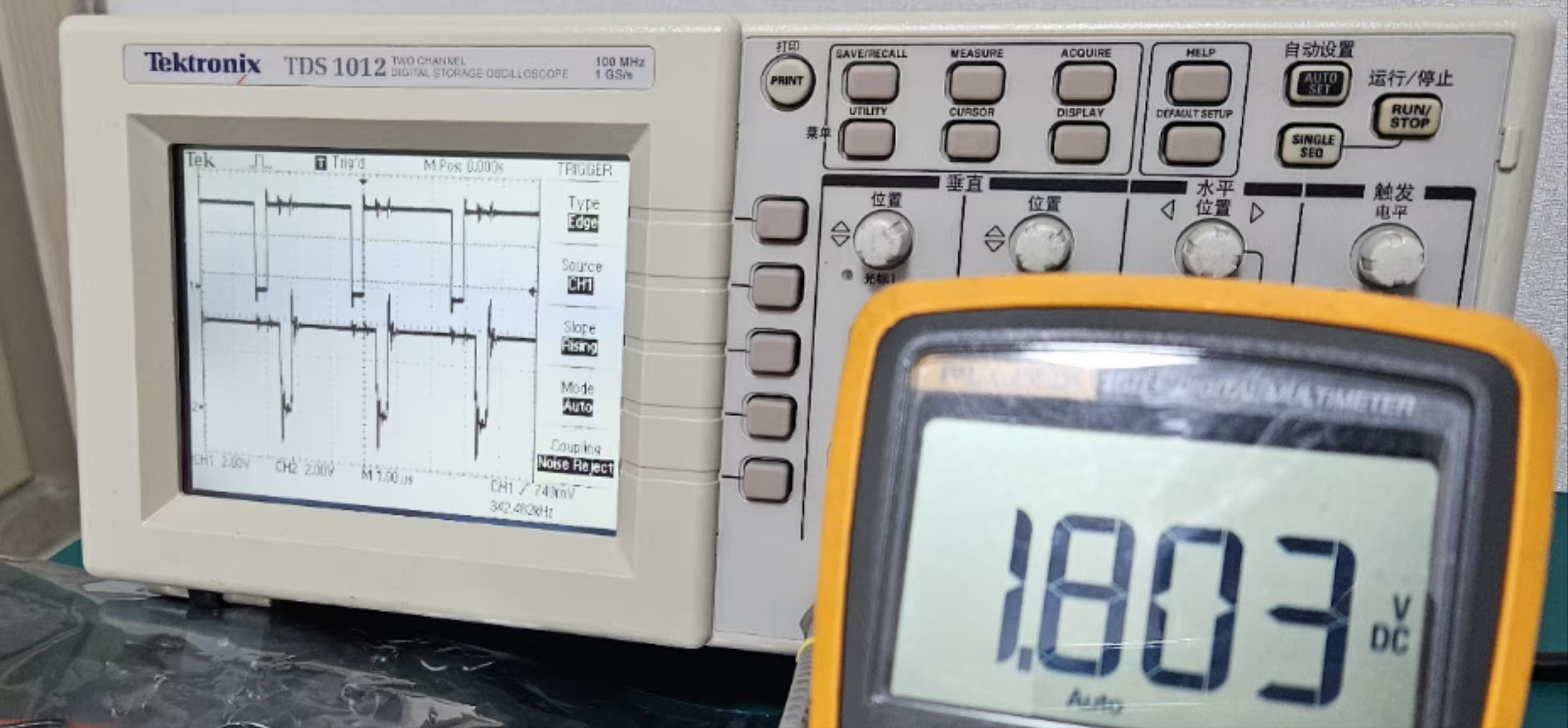
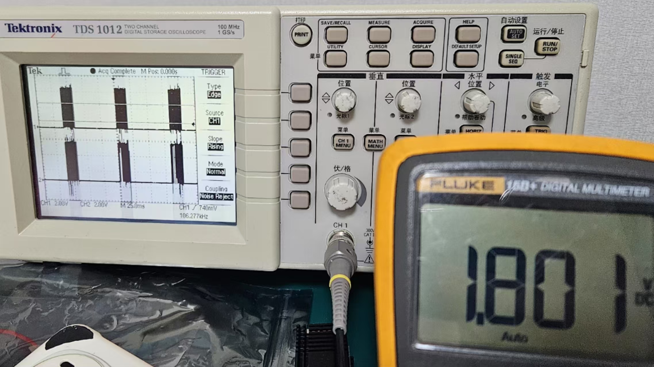
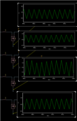
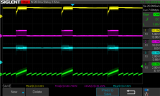
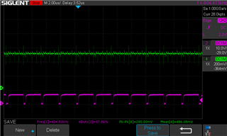
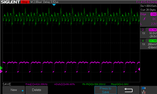
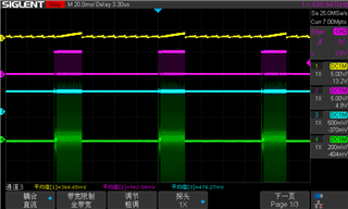
then i give voltage directly to the comp input, when voltage beyond 1.4v,pwm signal begin(just as i read from the forum),then the duty cycle quickly rise and get into the discountious mode,when voltage beyond 2v,pwm rise to max and didn't shutdown again。

can you give me some guides to figure it out,thanks

  • Hello,

    Sorry but let me better understand. Do you mean you forced the COMP pin by external voltage 1.4V to 2V? And it is working in this case? The PWM signal are normal as expected?

    Regards

  • Thanks for your replay!

    Yes,FB & DROOP connect to REF directily。COMP forced by external voltage generated by Opamp circuit with limit between 0.5 V~ 2.9 V。

    When didn't EN ucc27223 ,FB >1.4V PWM signal begin to generate, oscilloscope's channel 1 = PWM1 ,channel 2 = PWM2,The multimeter shows the voltage at FB point

    when FB voltage is 1.8V ,PWM reached it's maximum duty cycle

    when EN ucc27223 ,The PWM signal begins to become discontinuous

    then i change channel 2 = SS,The results show that some kind of failsafe seems to have been triggered

    I think there is something wrong with my CS1~4 circuits?

    I used a 1.5 milliohm sampling resistor in conjunction with an instrumentation amplifier to obtain the current value for each phase. The sampling resistor is placed after the inductor. The REF terminal of the amplifier is connected to CSCN and set to 0.7V through a resistor divider circuit. The sampling gain is currently 1.5 mV/A and the ILIM voltage is currently set to 0.460 V.a 1kΩ resistor is added between instrumentation amplifier's output and CSX in。

  • I think i found the problem,the inductor didn't match my load。

    1 uH ichoose,400 khz each phase,when VDCin=5V ,duty cycle at 50%。1 Ω load。

    in this condition ,inductor current drop to negative ,like DCM mode。


    It seems I need to use a lower load resistor and a higher current setting to ensure continuous inductor current.

    iIn addition, I found that the ucc27223 of some channels will lock B and turn off the upper and lower MOS tubes after being PWM turned on repeatedly in this situation

    Will this situation trigger the chip's fault protection measures?

    Thank you in advance for your time.‌ 

  • Hello,

    great you made some progress! I was off last week. Can you please make it clear what is the issue you are facing now?

    Regards

  • delighted to receive your response!

    i wonder if csx output negative because some phases' inductor current drop to zero and then become negative。Is that situation will trigger some protection?

  • Hello,

    what happens exactly? Is it shutting down and need to recycle the power to turn it on again?

    Regards

  • Hi,here is some wave

    channel 1:Vin 

    channel 2:TPS40090 PWM 1

    channel 3:TPS40090 COMP

    channel 4:TPS40090 SS

    Rload=0.5 Ω ,Apply Vdcdc_in ≈3.10V ,it's work at maximum Duty ,PWM signal continued

    When increase Vdcdc_in  at some point,PWM signal began to discontinued,The voltage on the SS terminal starts to charge repeatedly, it looks like some kind of fault protection is triggered。Because I have forced the FB terminal voltage = REF, the over-voltage and under-voltage protection will not be triggered. So the only possibility is that the overcurrent protection is triggered?

    Then i check the CSCN voltage ,It seems that some problems have been discovered

    channel 2:TPS40090 CSCN

    channel 4:High-side gate voltage of PWM4

    When shutdown Vdcdc_in【VDCDC_in is only connected to the upper-side input of each phase】 ,Only control voltage,CSCN = 0.486 V

    When Vdcdc_in=3 V,CSCN change to  1.04 V

    Then I checked my CSCN circuit. I used a voltage divider resistor to generate a reference voltage of 1.5 V, as shown in the figure below, but it seems that the CSCN pin of TPS40090 has a large sink current, causing the actual voltage to not reach 1.5 V and has fluctuations.
    So CSCN needs to be connected to a low internal resistance voltage source? Is it possible to adjust the voltage dividing resistor to the hundred ohm level?

    I don't know if this is the reason for PWM discontinuity.

  • Hello,

    I'm not sure what is the impedance on CSCN pin. From your experiment, the 1.5V reference voltage, from the voltage divider, is changing means the CSCN has low impedance. I think changing the voltage divider to hundreds Ohm will make the 1.5 ref more stable.

    Regards

  • Hi,thanks for your reply!

    maybe a 1.5v AA battery is a good choice for stable cscn :-)

    I'll try it and see if the problem solved

  • Hi,Now i confirmed it's a over current protection.

    Channel 1:TPS40090 SS

    Channel 2:TPS40090 PWM1

    Channel 3:TPS40090 ILIM ,Set to about 473 mV

    Channel 4:INA849 CS1,【I connect the CSCN directly to AGND finally】

    When PWM continued ,CS1 wave strange (Not saw wave as simulate)

    Then I increased Vdcdc_in until PWM discontinued,

    Noticed some spike on CS1 causes PWM1 shutdown prematurely。

    Zoom out:

    I checked PCB layout,there should be some problems with my AGND and PGND layout,which lead to poor cs wave.

    I think I need to redesign this project.

    Thank you very much for your answer!