This thread has been locked.
If you have a related question, please click the "Ask a related question" button in the top right corner. The newly created question will be automatically linked to this question.
Tool/software:
I've following questions related to HV-LV converter:
1. In TIDA-020031, how it is ensured that LV battery is charged in cc cv mode?
2. In EV architecture the HV-LV DC DC converter comes before the LV battery BMS?
3. Generally, for LV battery the CC CV charging is done through the control or a seperate circuit is needed?
Hello,
I have searched the e2e and found this thread saying that TIDA-020031 has been removed from ti.com.
The thread also states that there seems to be schematic errors with TIDA-020031 design. Please see the thread for details.
The following link will bring you to a battery charger that uses CC and CV, I would suggest that you use this design over the TIDA-020031.
https://www.ti.com/tool/PMP8740
Answers to your question below.
1. In regards to CC CV designs when the output votlage is below the regulated voltage the design is working in CC mode. When the output is in regulation the design is opperating in CV mode.
2. Yes
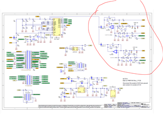
3. If using the UCC28951 to achieve constant current constant voltage mode will require extra circuitry. The extra circuitry required is circled below. This schematic was taken from PMP8740.
Thank you for interest in Texas Instruments (TI) products. If you have a related question, please click the "Ask a related question" button in the top right corner. The newly created question will be automatically linked to this question.
Regards,