A related question is a question created from another question. When the related question is created, it will be automatically linked to the original question.
If you have a related question, please click the "Ask a related question" button in the top right corner. The newly created question will be automatically linked to this question.
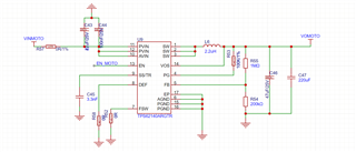
Please help to check whether there is any problem with the schematic diagram. If there is any modification, please help to explain in detail. Thank you!
Overall is good to me. It is better to change inductor to 1uH and COUT47uF to 22uF. This can help to have more suitable LC corner frequency for bettter loop stabilty. Because i see the there is a EC=220uF.
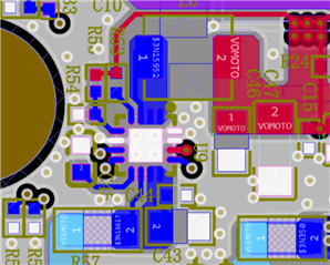
Please help to check whether the Layout is correct.
TPS62140ARGTR chip circuit input 6v, the output voltage is normal; But the 7v output voltage has been falling, I do not know whether it is the chip itself