This thread has been locked.

If you have a related question, please click the "Ask a related question" button in the top right corner. The newly created question will be automatically linked to this question.

UCC28951-Q1: PMP8740 - CC CV control circuit

Part Number: UCC28951-Q1
Other Parts Discussed in Thread: PMP8740, UCC28950

Tool/software:

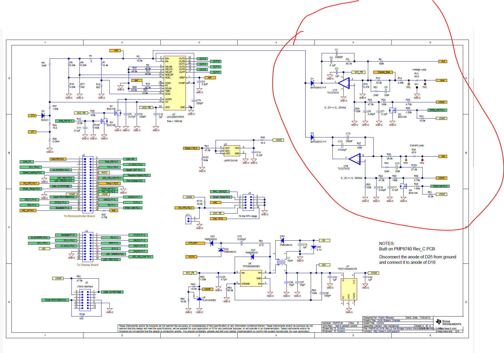
I want to understand the working and design of CC CV control circuit in PMP8740 reference design, but design guide is not available for this reference design. Please, help me to understand the design.

  • Abhishek,

    Which part of the circuit needs further elaboration? Do you mean how to set the component value to achieve different CC CV threshold?

  • Thanks for your reply Ning Tan. Yes, I know the component sizing and I would like to understand-

    1. From one of the TI support thread, I found that role of R102 27.4k ohm resistor in CC control is to avoid saturation of op-amp output at startup. In this I want to understand how exactly it is avoiding that situation.

    2. In EV the HV to LV DC-DC converter is used for charging LV battery plus to supply load to other auxiliary loads. Since, in PMP8740 CC control is designed for charging battery only which is the only load there. What modification I need to do in CC CV control in case other loads are also present?

    3. What will be the Vref value for voltage loop in CC mode interval?

    4. What will be the Iref value for current loop in CV mode interval?

  • Abhishek,

    I will assign this ticket to the PMP8740 owner for further support.

  • Ning, 

    Thanks for assigning this ticket.

    Please consider that I am on vacation until January 6th, so my replies maybe delayed.

    Abhishek,

    Regarding PMP8740, there is a design guide (but doesn´t cover the calculation about all components of this reference design because it would be too long) under the UCC28950 product page, see links:

    Power point presentation: https://www.ti.com/lit/pdf/slup349

    White paper: https://www.ti.com/lit/pdf/slup348

    In addition, please find below my replies to your questions:

    1. When the converter starts, the microcontroller starts also in three-state outputs. For this reason R51 is keeping biasing Q4 into a ON state, therefore forcing the Vds of Q4 to be zero. Now, since the average value of Vds (by means of RC-RC filter R45, C17, R44, C16) is actually the current reference (pin 5 of U1B), if during startup the PSFB controller UCC2895x is enabled, and if there is s small current or voltage offset between the two pins 5 and 6 of U1B, this small offset might bring in saturation (to zero or to VCC) its output. By adding a small bias to pin 6 of U1B, we are sure that the output pun 7 stays always at zero when the UCC2895x is enabled. The value of R102 can be calculated by resistive divider between R102 and R39 (as source) compensating the voltage and current bias current into pin 6 of U1B.

    2. You don´t need to do any modification to the CC CV control loops of PMP8740, because, if the output current is below the CC level (defined by current reference, ranging 0 - 2V, for Iout 0 - 60A), the voltage loop will be active and the converter will behave like a normal voltage-controlled power supply....just like a normal lab bench power supply.

    3. The Vref value for voltage loop in CC mode interval should be selected so that the equivalent Vout is higher than the maximum output voltage in constant-current mode. Let´s do an example. You have a 12V battery and want to charge it at 10A constant current. Depending on the type of battery, the maximum voltage on it will be defined in advance. In the case of Lead-Acid, it´s 14.4V. In this case set Vref for the voltage loop to 14.4V and Iref for the current loop to 10A. When the converter is enabled, the output voltage will not be 14.4V but just the voltage the battery has on that state of charge, for example 12.8V. The current will be limited to 10A and the voltage increases slowly until reaches 14.4V. At this point, two loops CC and CV will swap themselves, and the voltage will be defined by the DC/DC converter and not anymore from the battery. The charging current in this case will start reducing until it reaches a minimum value. Normally after the current is reduced to this minimum value, also the setting point of the voltage is reduced to avoid generation of gas from the battery....but this is related to the charging strategy, dependent on the chemistry.

    4. This point can be explained as reciprocal from point 3, as bot CC and CV loops exchange.

    Best regards,

    Roberto

  • Thanks Roberto

    Please check the answer for 2nd question. My question was in case the loads connected to the module are 1 battery + 2 auxiliary load and i want to charge the battery at 10A in CC. In this case how can i ensure with the current CC CV control that battery will charge at 10A current? What will be the Iref to drive all loads?

  • Hi Abhishek,

    Sorry, I misunderstood your question #2 :-).

    In order to supply other loads at the output of the battery charger, you can either add an auxiliary winding on the transformer or add a Buck converter with its input connected to the main output (which is normally the battery). In both cases the voltage will be variable because these voltages depend on the battery state of charge (SOC). This is why you need a post regulator to stabilize the voltage supplied to and auxiliary output.

    I hope now it´s a bit more clear.

    Thanks,

    Roberto

  • Thanks Roberto