This thread has been locked.

If you have a related question, please click the "Ask a related question" button in the top right corner. The newly created question will be automatically linked to this question.

BQ40Z50-R2: BQ40Z50-R2

Part Number: BQ40Z50-R2
Other Parts Discussed in Thread: BQ40Z50, EV2400, BQSTUDIO

Tool/software:

We have developed a BMD circuti based on BQ40Z50. It manages 4 LIFE batteries, connected in series.

It happens that we receive a battery from the field that cannot be recharged any more.

The BMS is working, but even if connected to power, the current consumption is zero.

The SMB bus (using EV2400) reports more than 60% of SOC.

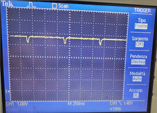
Furthermore, looking at the pack output, we see 5V with a pattern of drops every 1500ms. See picture below

8244.bq.log

The BMS is responsive, we read the registers, we can toggle LEDs. 

I am attaching the log files captured by bqStudio and BMS schematic. 

05_SPYFLY_BMS_Rev2_Schematics.pdf

Do you have any idea what happened to the pack?

Thank you very much

Kind regards

Andrea

  • Hi Andrea,

    If possible, can you please share the .gg file of the gauge settings so we can take a deeper look?

    Regards,

    Anthony

  • Hi Anthony,

    thank you for your reply. Please find the GG file attached.

    Kind regards

    Andrea


    TOKBO_GoldenImage_24_10_22.gg.csv

  • Hi Andrea,

    Thank you for sharing, it does not seem like there are any protections that are being triggered that would inhibit the gauge from receiving a charge. Since FET_EN is enabled as well, the CHG FET should become active once a current greater than the CHG Current Threshold has been observed as well. 

    Was this log file taken while a charge was attempted? Can you give more details about the load being applied for the charge?

    Regards,

    Anthony

  • Hi Anthony,

    the GG file I sent you earlier was the GG file we program on a new pack and WAS NOT the gg file of the not working (not receiving any charge) pack. In the meantime I have received from the field 5 packs that are in the same condition. THey respond to the I2C, but they do not accept any charging and they do not deliver any power.

    I have downloade from each one of them the memory (export from DATA MEMORY page) and also recorded few lines of log. Everything is inside the archive attached.

    Thank you for having a look

    Kind regards

    Andrea

    GG files.rar

  • Hi Andrea, 

    Thank you for sending these files, based on the log files, it seems as if there are no protections being triggered at the time the log was taken, and that from the gauge perspective the CHG and DSG FETs are active since the CHG and DSG bits are set. Would it be possible to see if there is any damage to the FETs on the device, and whether any protections become triggered once a charge/discharge is applied? This would be able to be seen from any of the bits in the SafetyStatus() registers becoming set.

    Regards,

    Anthony

  • Hi Anthony. 

    Investigating further was complex, as the battery pack circuit is not accessible as it is covered by resin. We succesfully removed the resin and we discovered that on every unit the problem was the 10 Ampere fuse (F1 in the schematic attached). Not sure what happened in the field, but for sure enough current  flowed in the fuse to blow it.

    So we wondered why the SCD protections did not trigger, preventing the fuse from blowing. We realized that SCD1 / SCD2 registers had a value of 0x77 and 0xe7. It is visible in the gg files I shared.

    If I am not wrong, this means a 100 Ampere treshold that looks to me to be too much.

    We have reduced the value to 0x00: maximum speed and minimum current: 22A and we confirmed that the discharge mosfet cuts the output well before the fuse is compromised.

    Do you have any advise on the values for these registers?

    Thank you

    Kind regards

    Andrea

    SCH - DBMS_Rev1_2020-12-07(1).pdf

  • Hi Andrea,

    Thank you for the update, what is the sense resistor value being used here so we can confirm the thresholds for these protections?

    Regards,

    Anthony

  • Hi, it's 0.001 ohm. 

    Full shcematic has been uploaded with my previous message, for your reference. 

    Thank you!

    Andrea

  • Hi Andrea,

    Thank you for confirming, I believe it is the correct idea to reduce the current threshold of this protection to protect the FUSE, however what is the typical application discharge current of the device? Since the ASCD protection is a hardware protection, it will have to go through more conditions after tripping to recover. The Overcurrent in discharge protection could also be used to disable the DSG FET, and since it is a firmware protection, it should be able to reset based on the current dropping.

    Regards,

    Anthony