This thread has been locked.

If you have a related question, please click the "Ask a related question" button in the top right corner. The newly created question will be automatically linked to this question.

TPS568231: How to measure loop response in the loop analyzer?

Part Number: TPS568231


Tool/software:

Hi Team,

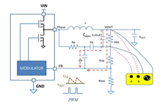
Customer have measured our loop response of our TPS568231, but they meet some issue in the test.

  • How to precise measure the loop response in TPS568231?

Here is the Bode plot of TPS568231, Could you see any issue in this response?

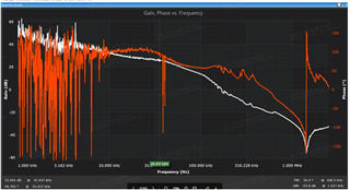
  • How COT control method effects the loop response of TPS568231?
  • Why we have oscillation in low frequency?

Thank you,

Yishan Chen

  • Hi Yishan, 

    The Gain curve looks fine. The only standout issue to me is the large phase spike around 35kHz. The oscillations at the low frequency could just be a product of the settings. There is a setting that "unwraps" the phase plot so that the curve does not switch between the top and bottom of waveform when it crosses 180deg.

    Unwrapping the phase would likely clean up alot of that low frequency signal. Please ensure the connections are made as pictured below and that you have a atleast a 10ohm resistor. You may try increasing the bode resistor value to clean up the curve. You may also try averaging the sweeps to clean up noise

    Best regards,

    Britton